Multi-parameter shaft analyzer (MPSA)

a multi-parameter, shaft technology, applied in the direction of instruments, machines/engines, mechanical equipment, etc., can solve the problems of increasing the possibility of component failure, increasing the complexity of machinery design, and restricting the incorporation of sensor redundancy to ensure robustness

Inactive Publication Date: 2006-08-24
THE BOEING CO
View PDF10 Cites 22 Cited by
  • Summary
  • Abstract
  • Description
  • Claims
  • Application Information

AI Technical Summary

Benefits of technology

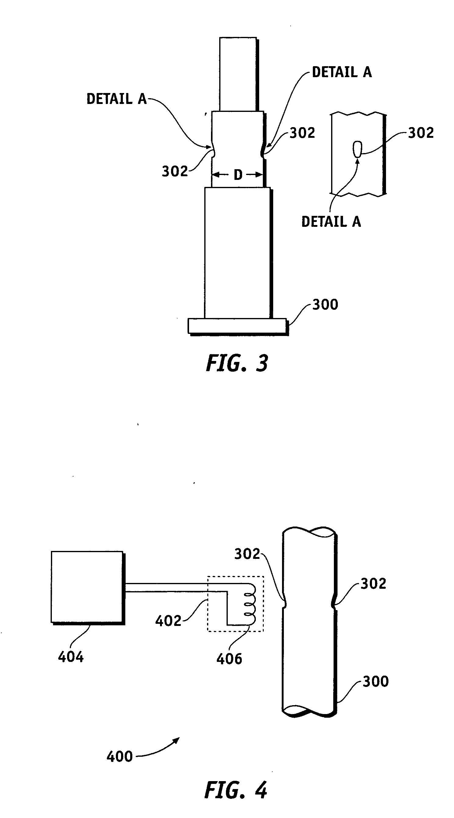
[0006] According to various exemplary embodiments, devices and methods are provided for measuring multiple parameters of a rotating shaft with one or more sensors. One embodiment comprises a rotating shaft configured with a pair of diametrically opposed depressions in the shaft body. A sensor is positioned in proximity to the rotating shaft depressions and is configured to generate an output signal related to movement of the rotating shaft and the depressions. A processor is configured to receive and analyze the sensor output signal and to determine multiple operating parameters of the rotating shaft.

Problems solved by technology

The incorporation of multiple sensors and multiple instrumentation ports into rotating shaft machinery can add to the complexity of the machinery design, electrical circuitry, and manufacture, and may also increase the possibility of component failure and restrict the incorporation of sensor redundancy to ensure robustness.
In the case of high performance rotating shaft machinery such as rocket engines, the use of multiple sensors and corresponding instrumentation ports can be particularly problematic since the multiple sensors can adversely affect the size and weight of the engine, and may also become potential leakage points.
As noted above, however, multiple instrumentation ports can be disadvantageous to an engine design with respect to complexity and reliability, thereby inhibiting measurements of this kind during flight.

Method used


Image

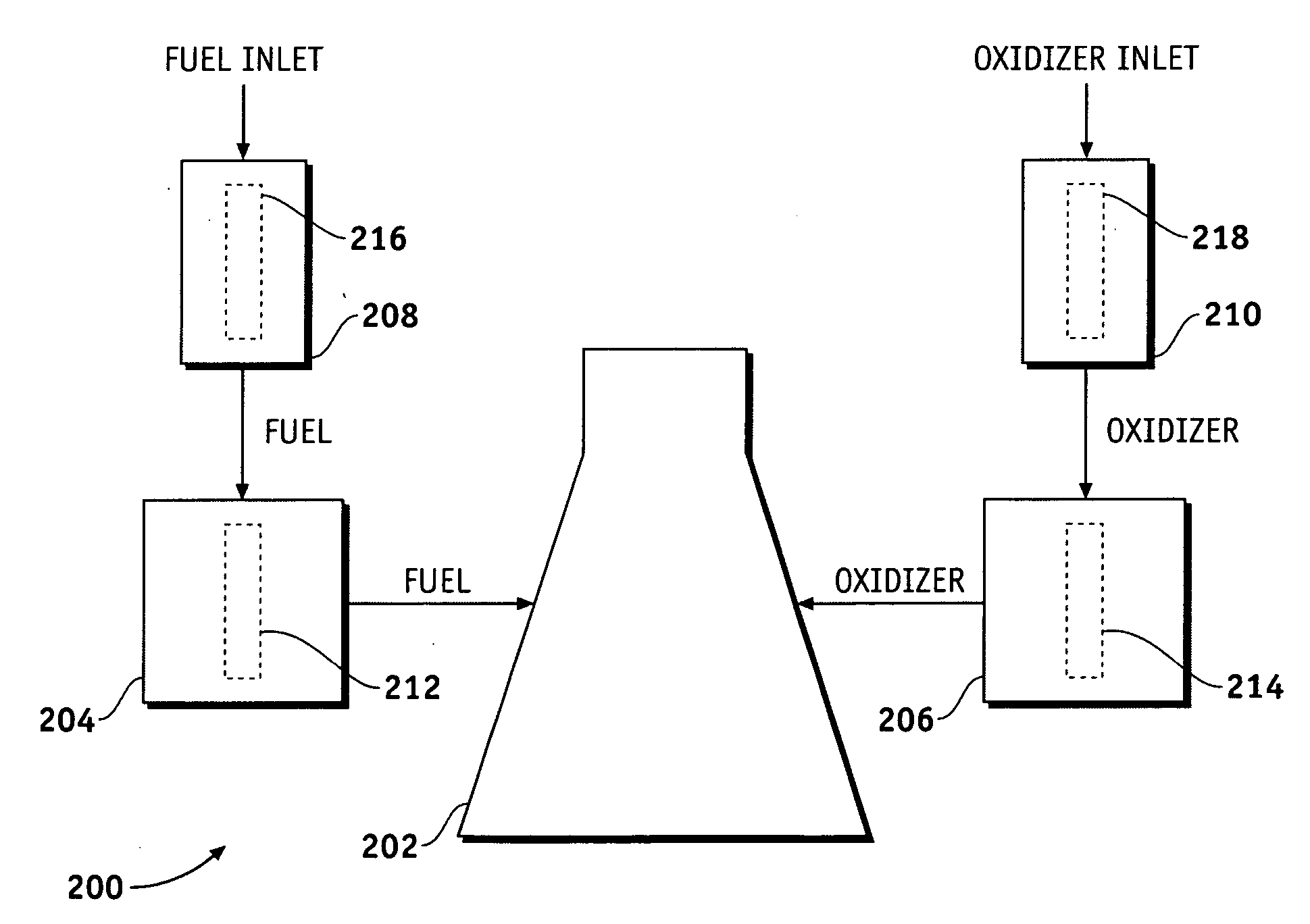
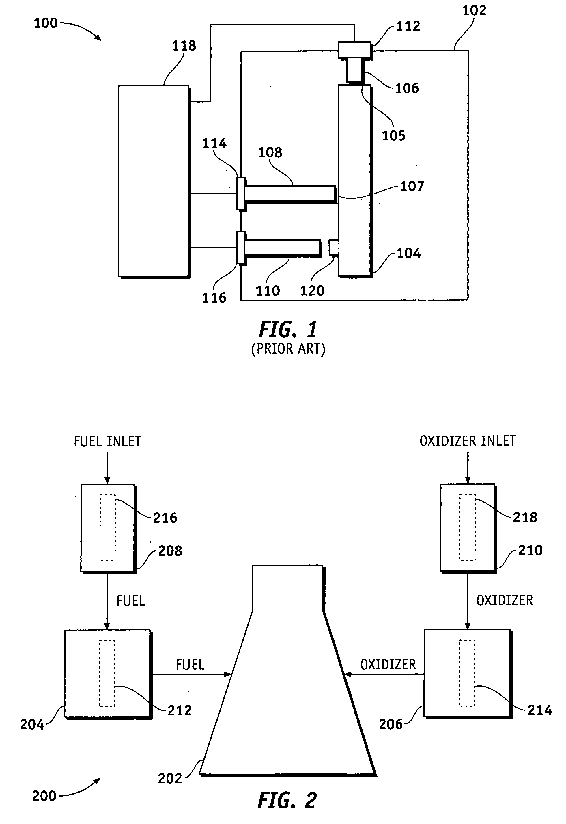
  • Multi-parameter shaft analyzer (MPSA)
  • Multi-parameter shaft analyzer (MPSA)
  • Multi-parameter shaft analyzer (MPSA)

Examples


Embodiment Construction

[0014] The following detailed description is merely exemplary in nature and is not intended to limit the invention or the application and uses of the invention. Furthermore, there is no intention to be bound by any expressed or implied theory presented in the preceding technical field, background, brief summary or the following detailed description.

[0015] Various embodiments of the present invention pertain to the area of monitoring the performance and health of rotating shaft machinery such as pumps, turbines, and motors. Typically, the rotating shaft parameters of interest include radial and axial displacement and speed, as well as others. The conventional use of a dedicated sensor and corresponding instrumentation port for each individual parameter can increase the complexity of a rotating shaft device, and can potentially degrade the reliability of the device. Therefore, a system for monitoring multiple parameters of a rotating shaft with a reduced number of sensors and instrum...


PUM

PropertyMeasurementUnit
diameteraaaaaaaaaa
depthaaaaaaaaaa
circumferenceaaaaaaaaaa

Abstract

Methods and apparatus are provided for measuring multiple operating parameters of a rotating shaft with a sensor. One embodiment of the apparatus comprises a sensor in close proximity to a matched pair of thumbnail depressions on the surface of a rotating shaft body. The thumbnail depressions enable the sensor to detect axial displacement and rotational speed of the shaft in addition to detecting radial displacement of the shaft body. Signal processing circuitry analyzes the sensor output data and computes separate values for the axial displacement, speed and radial displacement parameters. Additional filtering and signal processing techniques can be used to ascertain peak axial displacement, to reduce noise, and to compute other parameters, such as acceleration and power spectral density.

Description

TECHNICAL FIELD [0001] The present invention generally relates to instrumentation for rotating machinery, and more particularly relates to instrumentation for analyzing rotating shaft performance. BACKGROUND [0002] Many types of machinery including pumps, motors, generators and the like operate in conjunction with one or more rotating shafts. Conventional engines used in aerospace and other applications, for example, commonly include shafts that transfer mechanical energy from a motor or other power source to a propeller, fan or other load. Various types and sizes of rotating shafts are commonly used across a wide range of aerospace, transportation, industrial, governmental and other applications. [0003] Frequently, it is desirable to monitor certain operating performance parameters (e.g. rotation speed, radial or axial displacement, etc.) of a rotating shaft. Typically, these performance parameters are measured by individual sensors dedicated to a particular parameter. One sensor, ...

Claims


Application Information

Patent Timeline
Patent Type & Authority Applications(United States)
IPC IPC(8): G01L3/10
CPCF01D21/003F05D2270/304
Inventor DELCHER, RAY C.KHOSHNEVISAN, MOHSENSCHWARTZBART, AARONGOLDBERG, IRA B.
Owner THE BOEING CO
Why Eureka
Try Eureka