Engine decompression system

a technology of engine and compression cam, which is applied in the direction of engine starters, valve drives, muscle operated starters, etc., can solve the problems of difficulty in satisfying the decompression characteristics of conventional centrifugal mechanisms, the decompression cam projection height is decreased, etc., to achieve the effect of reducing the pressure within the cylinder bore during the compression stroke, improving the starting characteristics, and greatly reducing the starting operational load

Inactive Publication Date: 2006-08-24
HONDA MOTOR CO LTD
View PDF11 Cites 7 Cited by
  • Summary
  • Abstract
  • Description
  • Claims
  • Application Information

AI Technical Summary

Benefits of technology

[0011] With the first feature of the present invention, since in the complete combustion rotational region of the engine, the decompression cam shaft is maintained at the middle position in which the projection height of the decompression cam above the base face of the valve operating cam is made less than the projection height at the operating position, it is possible to stabilize the complete combustion state, thus improving the starting characteristics under load. Furthermore, owing to this arrangement, in the engine starting rotational region, the projection height of the decompression cam can be set at a level higher than that of the conventional arrangement and this enables the pressure within a cylinder bore during a compression stroke to be sufficiently decreased and, therefore, not only can the starting operational load be greatly reduced, but it is also possible to prevent dieseling effectively when stopping the engine.
[0012] Furthermore, with the second feature of the present invention, by means of the simple arrangement formed from the first weight, the second weight, and the return spring, it is possible to obtain appropriate two-stage decompression characteristics in which the projection height of the decompression cam is made to differ between the starting rotational region and the complete combustion rotational region.
[0013] Furthermore, with the third feature of the present invention, the decompression cam shaft and the first and second weights can be supported by utilizing the driven timing gear, and the decompression system can be made compact by disposing the first and second weights on opposite sides of the driven timing gear.

Problems solved by technology

However, in the engine decompression system, in order to minimize the cranking load when starting the engine, it is desirable that the projection height of a decompression cam from a base face of a valve operating cam is relatively large, and also in order to stabilize a complete combustion state in the engine, it is desirable that the projection height of the decompression cam is decreased, so that it is difficult for the conventional centrifugal mechanism to satisfy such decompression characteristics.

Method used


Image

  • Engine decompression system
  • Engine decompression system
  • Engine decompression system

Examples


Embodiment Construction

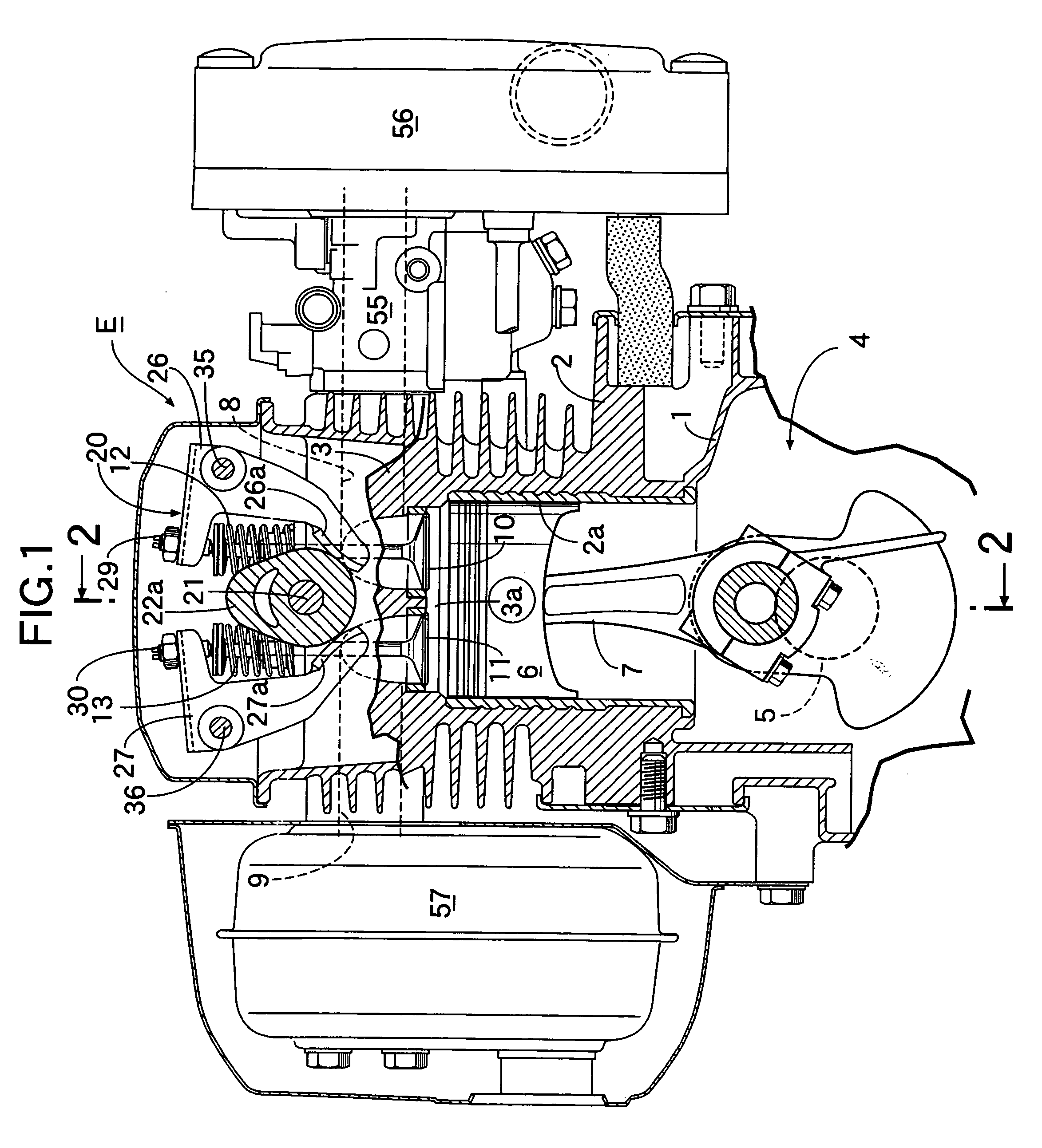
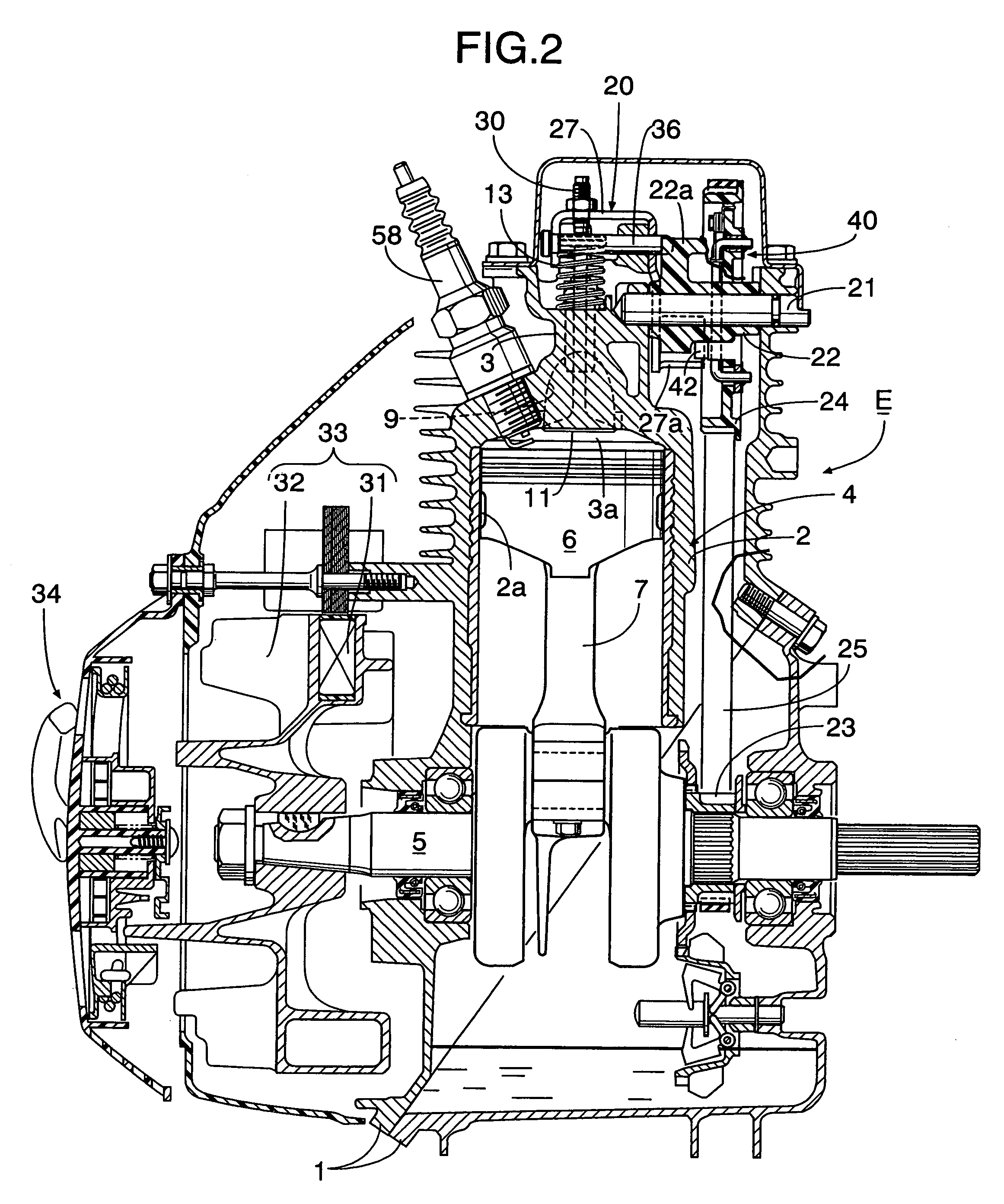
[0024] Referring first to FIG. 1 and FIG. 2, an engine main body 4 of a four-cycle engine E comprises: a crankcase 1 obliquely divided into two; a cylinder block 2 integrally connected to the upper end of the crankcase 1; and a cylinder head 3 integrally connected to the upper end of the cylinder block 2. A crankshaft 5 is supported on the crankcase 1, and is connected via a connecting rod 7 to a piston 6 that moves up and down within a cylinder bore 2a of the cylinder block 2. An intake port 8 and an exhaust port 9 are formed side by side in the cylinder head 3, and open in a combustion chamber 3a of the cylinder head 3. An intake valve 10 and an exhaust valve 11 for opening and closing the intake and exhaust ports 8 and 9 are mounted on the cylinder head 3. The intake valve 10 and the exhaust valve 11 are urged in a valve-closing direction by means of corresponding valve springs 12 and 13.

[0025] A valve operating mechanism 20 is provided on the cylinder head 3 to cause the intake...


PUM


Abstract

An engine decompression system that can secure a projecting height of a decompression cam from a base face of a valve operating cam to be relatively large in an engine starting rotational region, and maintain a state in which the projection height is decreased in a complete combustion rotational region of the engine. The decompression system includes a decompression cam shaft provided on a valve operating cam shaft or a rotating member integrally coupled thereto, the decompression cam shaft being capable of rotating between an operating position in which a decompression cam projects above a base face of a valve operating cam to slightly open engine valves during a compression stroke and a release position in which the decompression cam is withdrawn to allow the engine valves to close. A centrifugal mechanism connected to the decompression cam shaft maintains the decompression cam shaft at an operating position in a starting rotational region, and rotates the decompression cam shaft to the release position in a normal running region. The centrifugal mechanism is arranged so that, in a complete combustion rotational region between the starting rotational region and the normal running region, the decompression cam shaft is maintained at a middle position at which the projection height of the decompression cam is less than the projection height at the operating position.

Description

RELATED APPLICATION DATA [0001] The present application is based upon Japanese priority application No. 2005-44078, filed Feb. 21, 2005, which is hereby incorporated in its entirety herein by reference. BACKGROUND OF THE INVENTION [0002] 1. Field of the Invention [0003] The present invention relates to an improvement of an engine decompression system in which a decompression cam shaft is provided on a valve operating cam shaft equipped with a valve operating cam for opening and closing an engine valve or is provided on a rotating member integrally connected to the valve operating cam shaft. The decompression cam shaft is capable of rotating between an operating position in which a decompression cam projects above a base face of the valve operating cam so as to slightly open the engine valve during an engine compression stroke, and a release position in which the decompression cam is withdrawn beneath the base face so as to allow the engine valve to close. A centrifugal mechanism is ...

Claims


Application Information

Patent Timeline
Patent Type & Authority Applications(United States)
IPC IPC(8): F01L13/08F02D13/08F02N19/00
CPCF01L1/024F01L13/08F01L13/085F01L2101/00F01L2820/035F02N3/02F02N19/004F01L2301/00F01L1/02F01L13/00
Inventor SAITO, SHIGERUSUZUKI, TAKASHIMORIYAMA, HIROSHI
Owner HONDA MOTOR CO LTD
Why Eureka
Try Eureka