Laminating apparatus

a technology of laminated paper and abrasives, which is applied in the direction of mechanical control devices, instruments, process and machine control, etc., can solve the problems of reducing affecting recording or reproducing, and reducing the quality or lamination failure so as to prevent the decrease in the surface accuracy of the protective paper, the effect of avoiding effectively the conventional lamination failur

Inactive Publication Date: 2006-08-24
LINTEC CORP
View PDF3 Cites 36 Cited by
  • Summary
  • Abstract
  • Description
  • Claims
  • Application Information

AI Technical Summary

Benefits of technology

[0007] The present invention has been proposed in view of the problems. An object of the invention is to provide a laminating apparatus capable of inhibiting decrease in surface accuracy of the label by forming a label in the process of feeding out of the strip material, and by laminating the label immediately after being formed onto a disk-like information recording substrate to avoid effectively the conventional lamination failure caused from the line mark made by winding.
[0008] Another object of the invention is to provide a laminating apparatus with versatility, which achieves the manufacturing of the label and the manufacturing of the recording substrate laminated with the label with a single unit; thereby the manufacturing efficiency can be significantly improved resulting in a reduction of the manufacturing cost as well as the surface accuracy of the protective label can be prevented from being decreased.
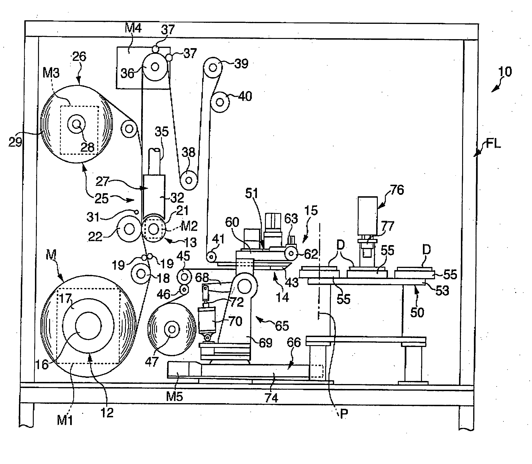
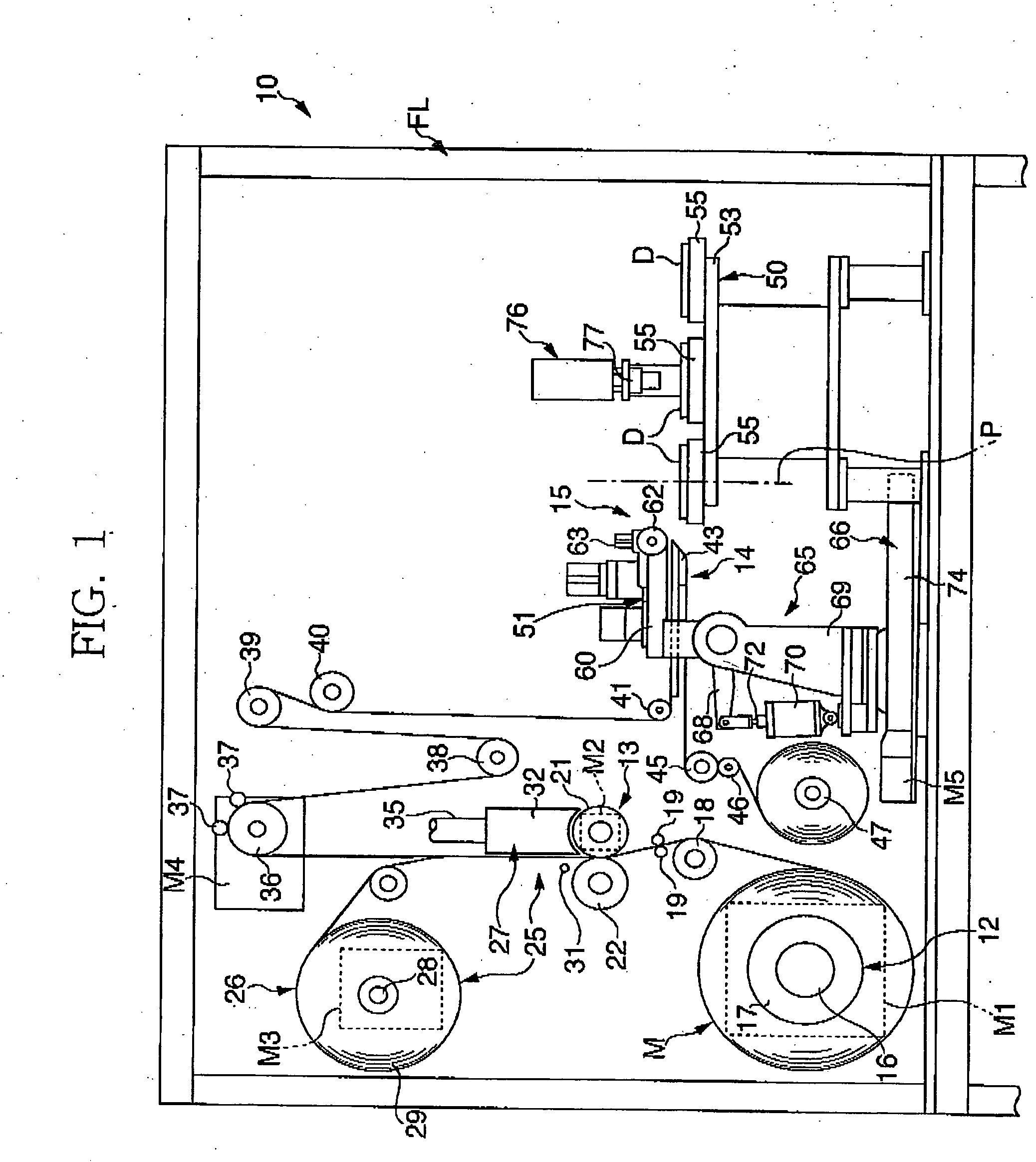
[0009] In order to achieve the object, the invention adopts such structure that a laminating apparatus for laminating a label on the recording layer surface of a disk-like information recording substrate comprises a feeding means for feeding a strip material applied with a film for forming a label on a base sheet, a pre-
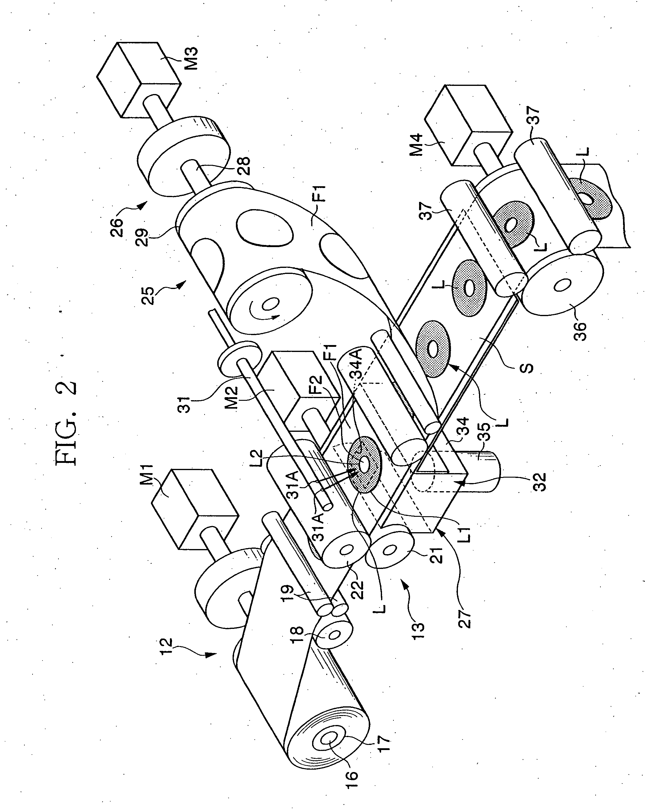
cutting means for forming a label by making cuts on the film in accordance with the plane shape of the recording substrate, a peeling means for peeling the label from the base sheet, and a label laminating means for laminating the peeled label to the recording substrate. In the structure, the strip material is constituted in a state that the film for forming the label is applied to the base sheet, and the strip material wound into a roll-like shape is consecutively fed out from the feeding means. The fed out strip material is formed with cuts into a plane shape corresponding to the shape of the recording substrate by the pre-cutting means at a position on its way. The cuts include an outer circular cut corresponding to the outer shape of the recording substrate and an inner circular cut corresponding to the central portion of the recording substrate. The outer circular cut is formed in the film and the inner circular cut is formed in both of the film and the base sheet. The label formed by the pre-cutting means is, after being peeled off via the peeling means, laminated onto the recording substrate by the label laminating means. Thus, since the label is formed from a master roll of the strip material, and is consecutively laminated onto the recording substrate in the next process after being formed, it is made possible to reliably eliminate the problems of the conventional apparatus, in which the label previously applied on the base sheet at predetermined intervals is fed out from a roll-like master roll and laminated onto the recording substrate after being peeled off therefrom.
[0011] Further, the second collection unit of the invention comprises a blowing means for blowing air to the inner film area, and a suction means for sucking the inner film area positioned at the opposite side of the blowing means. Owing to this structure, since the second collection unit can collect the inner film area without coming into contact therewith, the collection can be achieved reliably without requiring stopping operation or reducing the laminating efficiency.
[0012] The label laminating means comprises a stage that supplies the recording substrate to a predetermined laminating position, a label holding member that is provided movably with respect to the recording substrate at the laminating position and holds the label, and a pressing member that gives a predetermined pressing force to the label overlapped over the recording layer surface of the recording substrate by relative movement between the recording substrate and the label holding member. Owing to this arrangement, the label can be laminated with a specific pressing force when the label is laminated onto the recording substrate, and the laminating accuracy can be maintained satisfactorily.
[0013] Further, the laminating apparatus is arranged so that the label holding member is provided so as to perform a relative movement with respect to the surface of the recording substrate while holding the label in an inclined posture with respect to the surface of the recording substrate, and that the pressing member presses the label while moving from one end to the another end thereof to laminate the label onto the recording substrate sequentially. Here, the pressing member may comprise a roller capable of rotating on the label. Owing to this arrangement, it is possible to laminate the label while expelling air residing between the label and the recording substrate preventing the air bubble being caught therebetween.

Problems solved by technology

However, in the conventional laminating apparatus, since it is structured so that the protective label previously formed into a shape of the optical disk is fed out from a state that the same is wound along with the base sheet into a roll, generally a line mark made by winding resides in the protective label causing decrease in quality or lamination failure of the protective label.
Accordingly, due to the elastic deformation of the adhesive and the edges of the protective labels overlapped with each other, pressed trace (step) or pressed damage caused by the winding pressure is formed on the surface of the protective label resulting in a decrease of the surface accuracy of the protective label.
When the protective label having such pressed trace or pressed damage is laminated onto the optical disk, it may cause a considerably adverse effect on recording or reproducing.
Furthermore, since the manufacturing process of the protective label and the laminating process of the protective label are separated from each other, such inconvenience that the manufacturing efficiency of the optical disk itself is also decreased is resulted in.

Method used


Image

  • Laminating apparatus
  • Laminating apparatus
  • Laminating apparatus

Examples


Embodiment Construction

[0021] Now, one embodiment of the present invention will be described below with reference to the attaching drawings.

[0022]FIG. 1 is a view schematically showing the structure of a laminating apparatus according to the embodiment. FIG. 2 is a perspective view schematically showing a part of component parts shown in FIG. 1, of which layout is changed for the convenience of the description. Referring to these drawings, a laminating apparatus 10 is structured so as to be roughly received within a frame FL defining the outer shape of the apparatus. Provided in the frame FL are a feeding means 12 disposed to feed a strip material M wound into a roll-like shape, a pre-cutting means 13 for forming a predetermined cut in the strip material M fed out from the feeding means 12, a peeling means 14 for peeling a protective label L (refer to FIG. 2) formed by the pre-cutting means 13 from a base sheet S, and a label laminating means 15 for laminating the peeled protective label L to an optical ...


PUM

PropertyMeasurementUnit
tensionaaaaaaaaaa
speedaaaaaaaaaa
areaaaaaaaaaaa

Abstract

Using a strip material carrying a film for forming a label to a base sheet, cuts are formed in the film at a by a cutting means while feeding the strip material, and film areas excluding labels are collected. The labels are left on the base sheet and, after being peeled off at a peeling means, the label is sucked and held by the label holding member. The label is subsequently transferred to a recording substrate at a laminating position and is laminated onto a recording substrate while being pressed by a press roller. The strip material is motivated by a motor. A dancer roller disposed between the cutting means and the peeling means removes slack in the strip material, and a motor controller controls the speed of the motor based on the sensed position of the dancer roller.

Description

[0001] This application is a continuation-in-part of application Ser. No. 10 / 682,068, which was filed on Oct. 10, 2003.DESCRIPTION OF THE INVENTION BACKGROUND OF THE INVENTION [0002] 1. Field of the Invention [0003] The present invention relates to a laminating apparatus, and particularly, to a laminating apparatus suitable for laminating a film onto a surface of a recording layer formed on one side of an optical disk, which serves as an information recording medium. [0004] 2. Description of the Related Art [0005] Conventionally, an optical disk capable of storing and reproducing high volume information is formed with a recording layer on one side thereof and a light transmissible film is laminated to protect the recording layer. The lamination of the film is made using a master roll constituted by winding a strip material comprising a base sheet made of a consecutively extending release sheet or the like and protective labels laminated on one side of the base sheet at predetermined...

Claims


Application Information

Patent Timeline
Patent Type & Authority Applications(United States)
IPC IPC(8): B32B37/00B32B38/04B32B38/10B65C1/02B29C63/00B65C9/18B65C9/36G11B7/26
CPCB29C63/0047B29L2017/003B65C9/1869B65C9/36Y10T156/171Y10T156/1744Y10T156/1705Y10T156/1339Y10T156/17
Inventor HAYASAKA, TAKUYATSUKAMOTO, KATSUHIDE
Owner LINTEC CORP
Why Eureka
Try Eureka