Audio signal cable

a signal cable and audio technology, applied in the direction of cables, insulated conductors, conductors, etc., can solve the problems of insufficient bass, affecting the sound quality of the signal, so as to avoid skin effect and phase difference problems, high signal quality, and great flexibility

Inactive Publication Date: 2006-08-24
VICTOR JAY
View PDF10 Cites 6 Cited by
  • Summary
  • Abstract
  • Description
  • Claims
  • Application Information

AI Technical Summary

Benefits of technology

[0017] The various combinations of at least two different conductors within the cable of the present invention provide users with great flexibility in choosing the desired distortion effect produced by an electric instrument while maintaining high signal quality as well as avoiding skin effect and phase difference problems.

Problems solved by technology

Since balance is the most essential factor of high fidelity acoustics, when full-range balance is poor various problems result.
For example, insufficient bass makes people feel that music is muted and diluted.
Conversely, when bass is excessive, sound becomes too dense and even burdensome.
Sound becomes cold when midrange is lacking and overly warm when too much is heard.
At the same time, overall definition is decreased resulting in acoustic dispersion, sound alteration, and positional inaccuracy problems.
Also, when treble projection is inadequate, music becomes depressive, monotonous, and spatially confined, while the reverse situation results in a presentation that is too bright and lively.
However, if the conductor is too large, then high frequency signal passage becomes difficult.
Additionally, in conventional signal cables, skin effect is a challenging problem in that it commonly causes distortion and adversely affects signal transmission.
A major problem with the presently known cables is that these cables utilize conductors which are not designed to effectively carry more than one type of signal frequency.
For example, when such cables are used to simultaneously transmit at different bands of frequency (i.e., high, medium, and low frequencies), the problem of phase difference occurs.
While stranded wire is generally undesirable for high fidelity (Hi-Fi) sound reproduction, where maximum clarity, and lowest possible distortion is the goal, for guitar this is not quite the case.
However, there are no presently known audio cables that provide the distortion effect and that are capable of simultaneously providing additional sound enhancements which are desirable for electric instruments.

Method used


Image

  • Audio signal cable
  • Audio signal cable
  • Audio signal cable

Examples


Embodiment Construction

[0028] The following discussion describes in detail several embodiments of the invention and several variations of those embodiments. This discussion should not be construed, however, as limiting the invention to those particular embodiments. Practitioners skilled in the art will recognize numerous other embodiments as well.

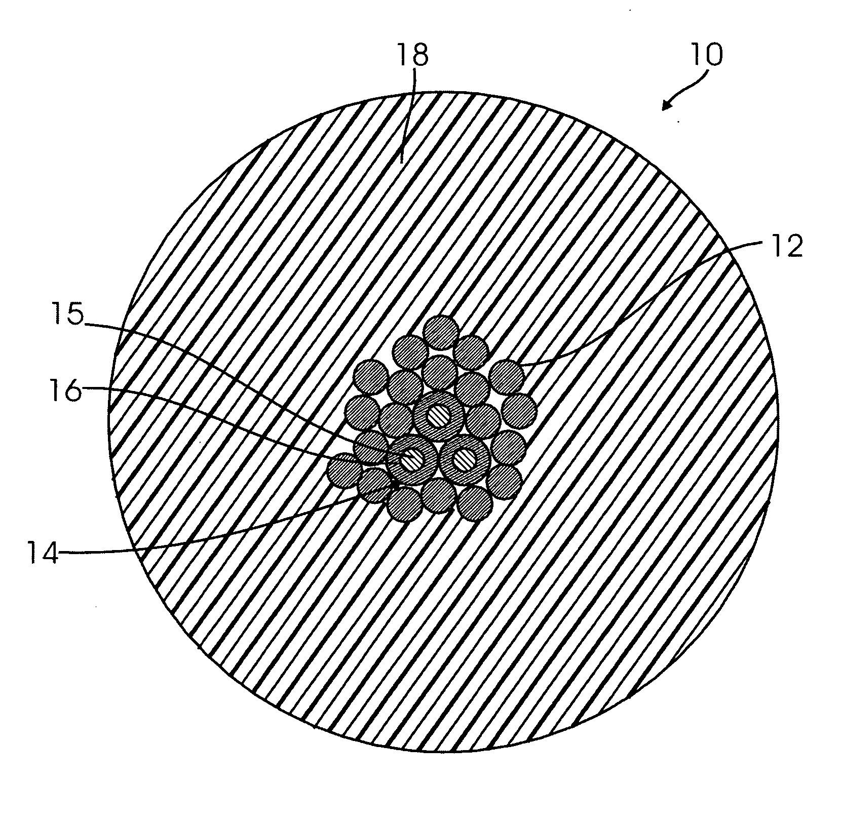
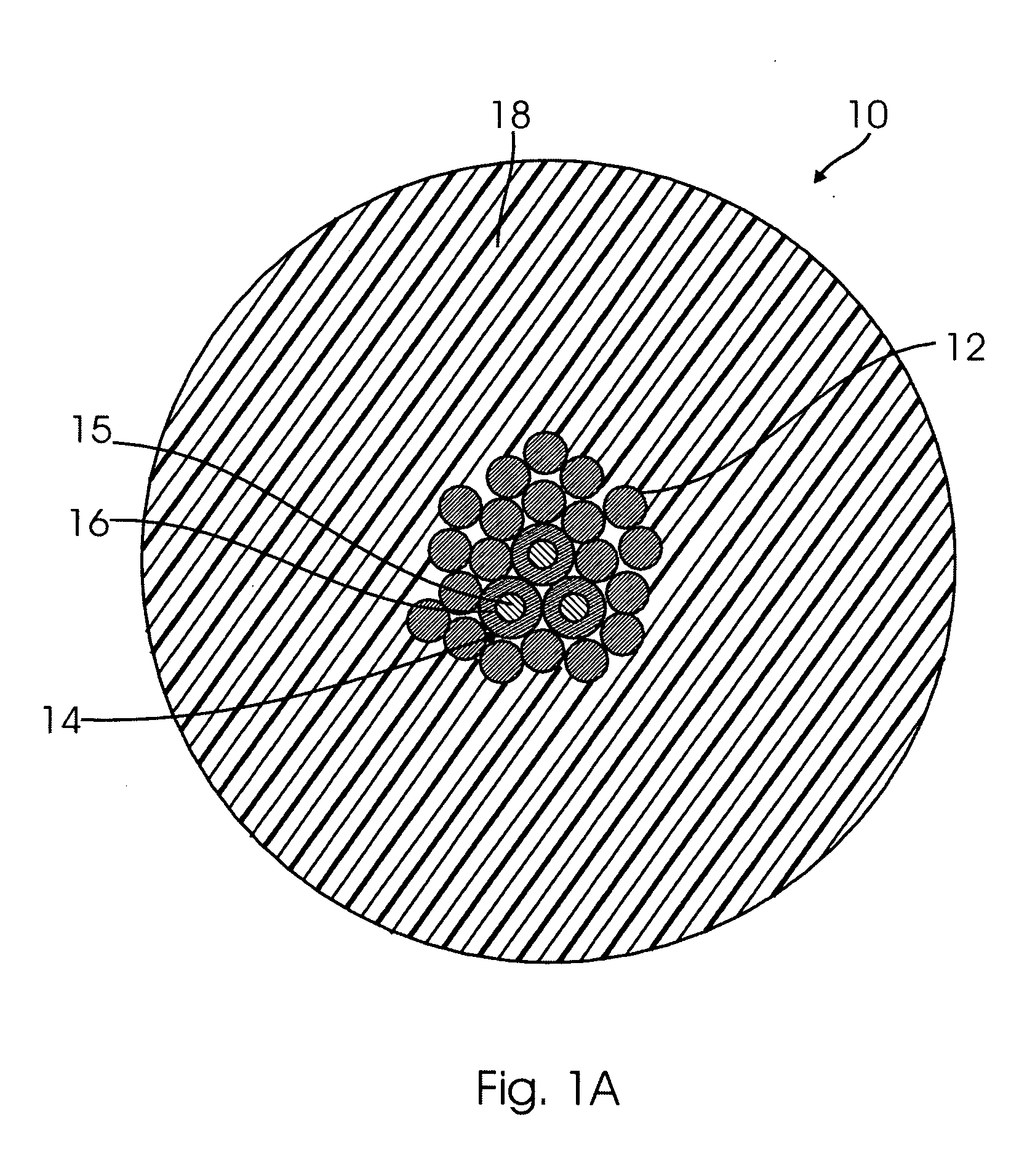
[0029] Referring to FIG. 1A, the cross-sectional drawing of one preferred embodiment of the audio cable 10 of the invention, stranded wire 12 comprises one conductor and tinsel wire 14 comprises another conductor. Although three tinsel wires are shown in the drawing, the number of tinsel wires may be varied in accordance with signal frequency ranges and harmonic distortion requirements. Tinsel wire 14 is shown as a polyethylene strand 15 covered by copper foil 16. The conductors within the audio cable 10 are surrounded by a common insulation 18.

[0030] Stranded wire refers to any two or more conductor wires which are individually uninsulated but which share comm...


PUM

PropertyMeasurementUnit
transmission currentaaaaaaaaaa
tensile strengthaaaaaaaaaa
outer diameteraaaaaaaaaa

Abstract

An audio signal cable consisting of various combinations of two or more distinct types of conductors. The cable contains at least two conductors of different types. The individual conductors within the cable may be individually insulated or uninsulated. The individual conductors may also be of varying shapes and sizes. The conductors are surrounded by a common insulation. Combining at least two types of different conductors within the cable provides the cable with a versatility to be adaptable to a wide variety of sound applications.

Description

CLAIM OF PRIORITY [0001] This application is a continuation-in-part and claims the benefit of the priority date of my co-pending application Ser. No. 11 / 049,062, filed Feb. 2, 2005, which is a continuation-in-part of my application Ser. No. 10 / 619,441, filed Jul. 16, 2003 (now U.S. Pat. No. 6,969,805), and incorporates the teachings of those two applications as if fully set forth herein.FIELD OF THE INVENTION [0002] The invention herein relates generally to electric audio cables, and more particularly, to signal carrying cables incorporating a plurality of conductors of varying types and shapes which in combination provide for the improved transmission of audio signals. BACKGROUND OF THE INVENTION [0003] Signal transmission requirements have become higher because of the greater fidelity and sensitivity of currently available high fidelity audio system equipment. Good signal cables support fine dynamics, separation, and rich overtones, but most importantly, they must have a very high...

Claims


Application Information

Patent Timeline
Patent Type & Authority Applications(United States)
IPC IPC(8): H01B11/02H01B7/30H01B11/12
CPCH01B7/30H01B11/12
Inventor VICTOR, JAY
Owner VICTOR JAY
Why Eureka
Try Eureka