Assembly for illuminating objects with light of different wavelengths

a technology of illuminating objects and parts, applied in lighting and heating equipment, lighting heating/cooling arrangements, instruments, etc., can solve the problems of unfavorable effects on observation and measurement, frequent change of light sources, and heat treatmen

Active Publication Date: 2006-08-24
CARL ZEISS MICROSCOPY GMBH
View PDF13 Cites 23 Cited by
  • Summary
  • Abstract
  • Description
  • Claims
  • Application Information

AI Technical Summary

Benefits of technology

[0016] It is furthermore advantageous when at least one LED is arranged exchangeably in the mount, e.g. in a suitable plug-in socket. In addition, at least one LED can advantageously be securely joined to the associated Peltier cooling element and can be exchangeably arranged in the mount together therewith. During an exchange, the LED, together with the Peltier cooling element, is then exchanged as a single unit. LED and associated Peltier cooling element can also be detachably joined to one another so that the LED can be exchanged without the Peltier cooling element.

Problems solved by technology

However, such sources of white light have a brief service life, so that the light source must frequently be changed.
These light sources are also characterized by the development of a good deal of heat, which can have unfavorable effects on the observations and measurements.
An additional disadvantage of these light sources is that it is not possible to turn them on and off rapidly, because the light sources tend to have an afterglow.
The disadvantage of this illumination device is that there is no provision for turning on and placing different LEDs in the illumination ray path of the microscope.

Method used


Image

  • Assembly for illuminating objects with light of different wavelengths
  • Assembly for illuminating objects with light of different wavelengths
  • Assembly for illuminating objects with light of different wavelengths

Examples


Embodiment Construction

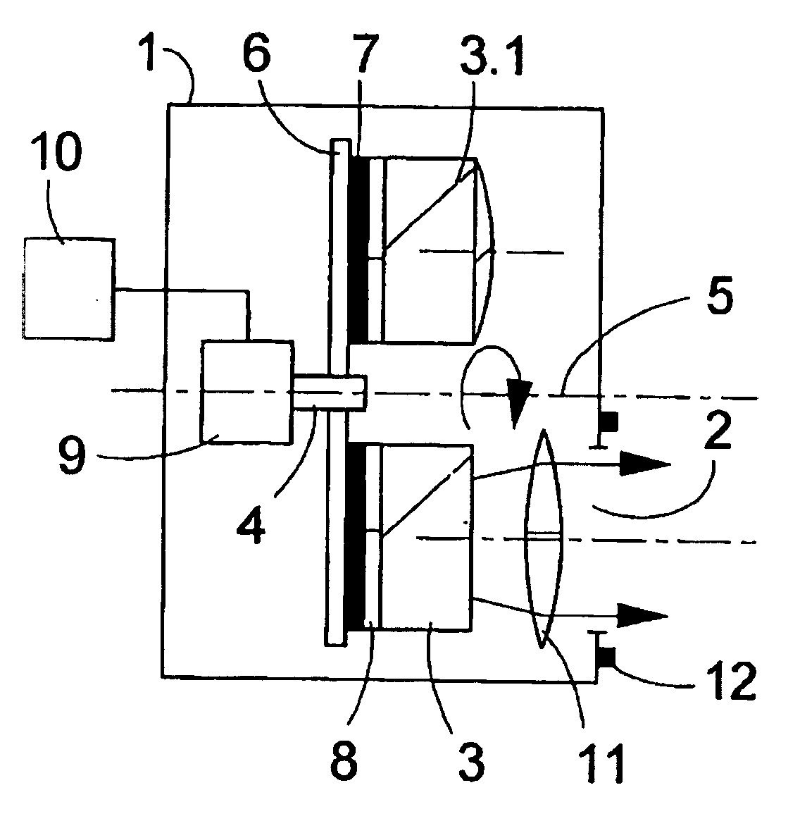
[0007] The object of the invention is to create a light source arrangement, in particular for fluorescent microscopes, that permits rapid and precise positioning of LED radiation sources that emit light of the same and / or different wavelengths one after the other in the illumination ray path of a microscope.

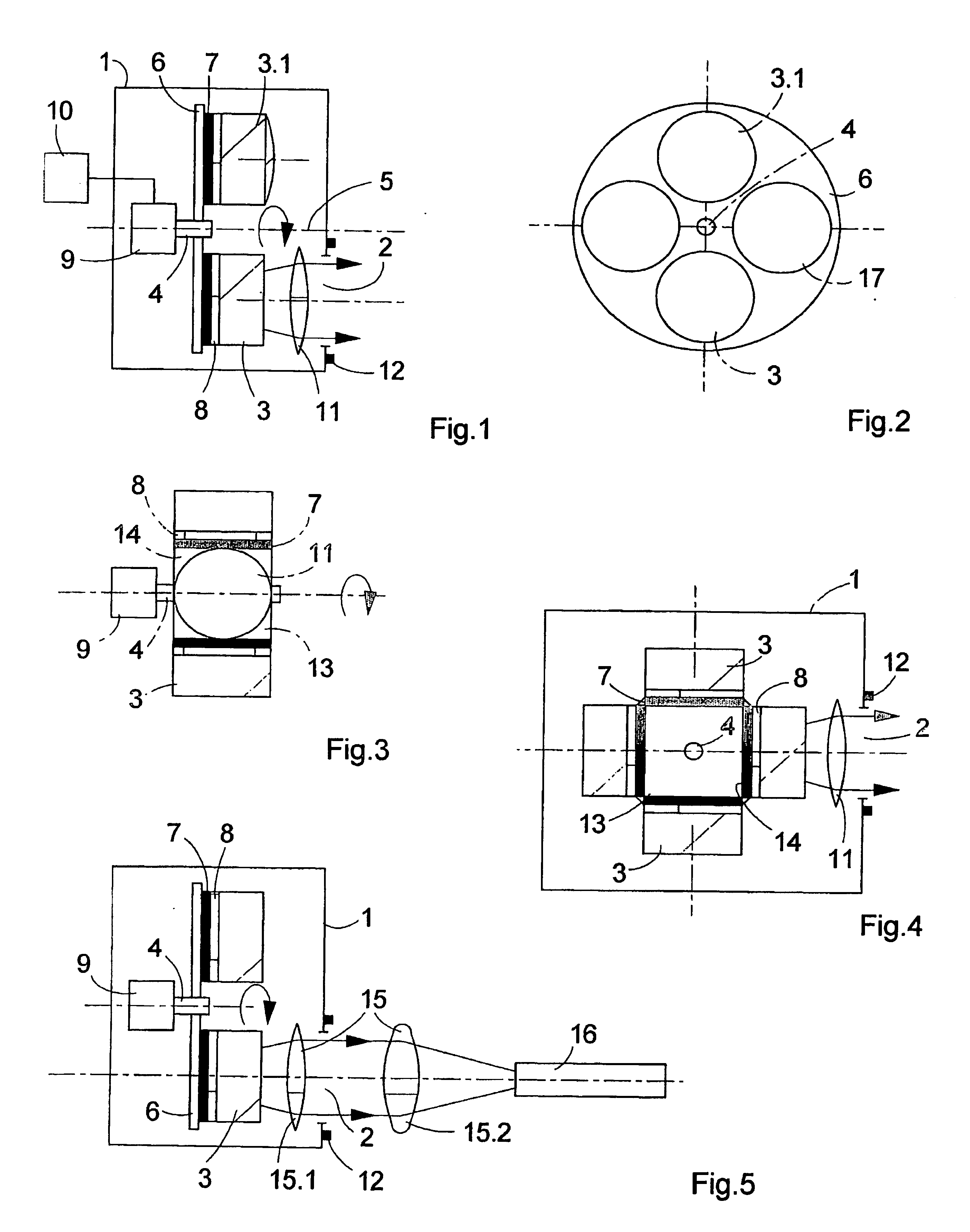
[0008] This object is inventively attained in an arrangement embodied in accordance with the preamble with the characterizing means of the first claim. Additional designs and details of the invention are disclosed in the subordinate claims. The receiving apparatus is advantageously embodied as a rotary table that is rotatable about the axis and on which the mounts are provided.

[0009] In accordance with a first embodiment of the inventive arrangement, it is advantageous when the mounts are embodied and arranged on the receiving apparatus and are attached to the receiving apparatus such that the main emission direction of the at least one LED arranged thereon runs parallel to the...


PUM


Abstract

The invention relates to an assembly for illuminating objects with light of different wavelengths in microscopes, automatic microscopes and devices for fluorescent microscopy applications. Said assembly comprises LED light sources for illuminating the objects, which are positioned in the illumination beam path of the microscope or device. A receiving element (6; 13) that can be rotated about a rotational axis (5) is provided with respective fixing elements (7) for at least one LED (3; 3.1). The receiving device (6; 13) is situated in a housing (1) that can be placed on or positioned in the device housing (18). A drive unit (9) for the defined adjustment of the receiving device (6; 13) is provided in such a way that the LED (3; 3.1) can be positioned in front of a light emission opening of the housing (1) with the respective focal point wavelength that is required for measuring and/or observation purposes.

Description

FIELD OF THE INVENTION [0001] The invention relates to an arrangement for illuminating objects with light of different wavelengths in microscopes, automatic microscopes, and equipment for fluorescent microscopy applications, e.g. in readout equipment for titer plates and biochip readers. PRIOR ART [0002] In wide-field fluorescent microscopy, halogen or arc lamps are generally used as sources of white light in combination with spectral filters in order to bring electromagnetic radiation of suitable wavelengths for observation or measurement onto an object to be examined or onto a specimen to be examined. However, such sources of white light have a brief service life, so that the light source must frequently be changed. These light sources are also characterized by the development of a good deal of heat, which can have unfavorable effects on the observations and measurements. Furthermore, the spectral portions in the light sources that are not used must to a great extent be suppressed...

Claims


Application Information

Patent Timeline
Patent Type & Authority Applications(United States)
IPC IPC(8): B60Q1/00G02B21/06G02B21/16G02B21/28
CPCG02B21/06G02B21/16G02B21/28Y10S362/80
Inventor WESTPHAL, PETERBUBLITZ, DANIEL
Owner CARL ZEISS MICROSCOPY GMBH
Why Eureka
Try Eureka