

Zoom lens and image projection apparatus having the same
- Summary
- Abstract
- Description
- Claims
- Application Information
AI Technical Summary
Benefits of technology
Problems solved by technology
Method used
Image

Examples
embodiment 1
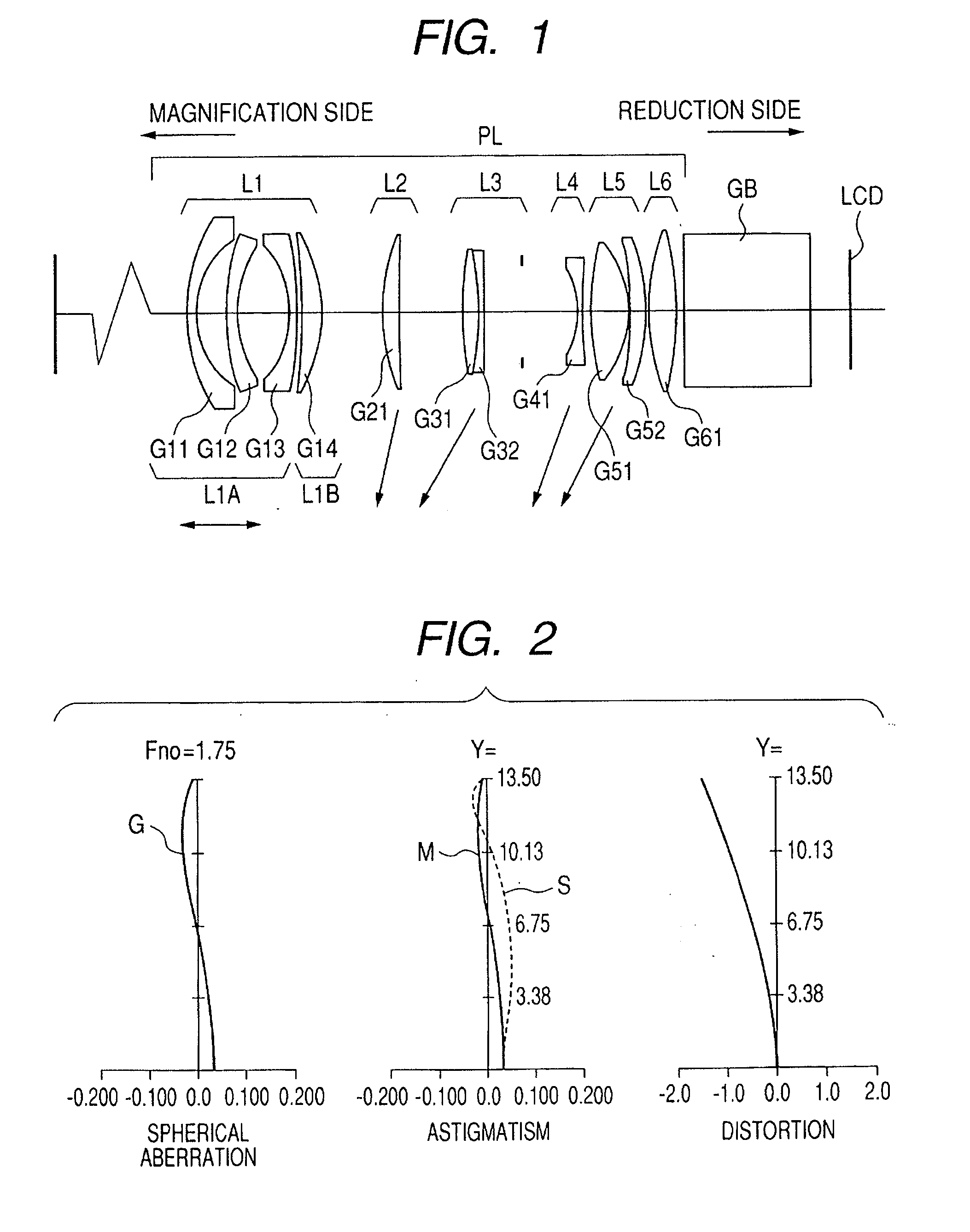
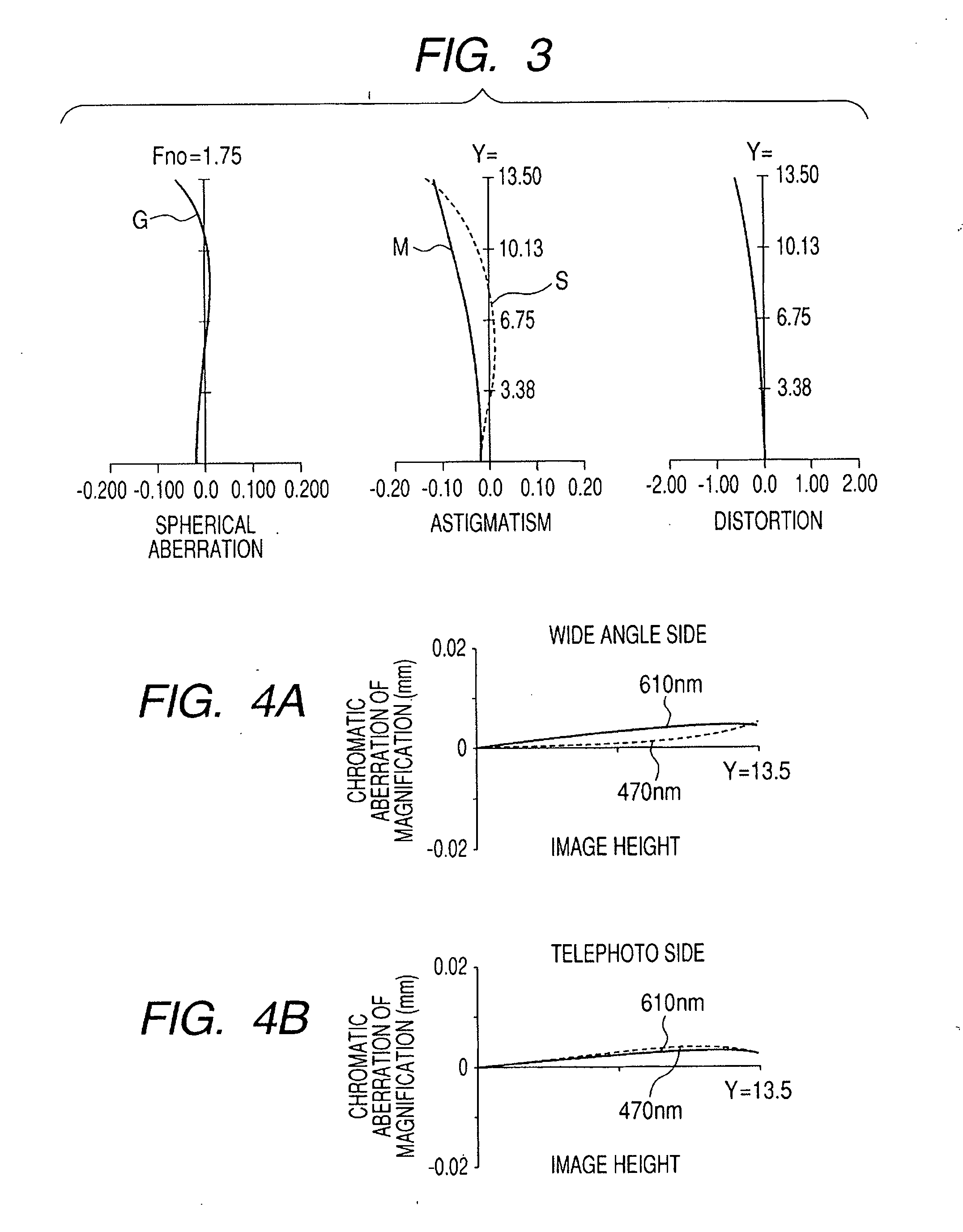
[0067]FIGS. 4A and 4B show chromatic aberrations of magnification of a wavelength 610 nm (red) and a wavelength 470 nm (blue) relative to the wavelength 550 nm of Numerical Embodiment 1, at the wide angle end and the telephoto end, respectively, at each image height Y when the object distance is 1.7 m.
[0068]FIG. 5 is a schematic view of the essential portions of an image projection apparatus using a zoom lens according to Embodiment 2 of the present invention. FIGS. 6 and 7 show aberrations at the wide angle end and the telephoto end, respectively, in a case of the object distance being 1.7 m when the numerical values of Numerical Embodiment 2 to be described later corresponding to Embodiment 2 of the present invention are represented by the unit of mm.
[0069]FIG. 8 is a schematic view of the essential portions of an image projection apparatus using a zoom lens according to Embodiment 3 of the present invention. FIGS. 9 and 10 show aberrations at the wide angle end and the telephoto...
embodiment 2
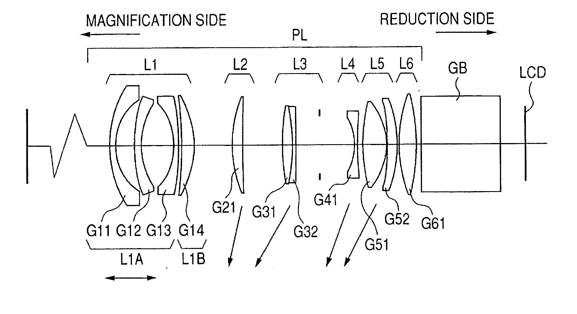
[0090] In Embodiment 2 shown in FIG. 5, L1 designates a first lens unit having negative refractive power, L2 denotes a second lens unit having positive refractive power, L3 designates a third lens unit having positive refractive power, L4 denotes a fourth lens unit having negative refractive power, L5 designates a fifth lens unit having positive refractive power, L6 denotes a sixth lens unit having positive refractive power, and L7 designates a seventh lens unit having positive refractive power.
[0091] The first lens unit L1 has a 1A-th lens unit L1A having negative refractive power, and a 1B-th lens unit L1B having positive refractive power.
[0092] In Embodiment 2, during zooming (magnification) from the wide angle end to the telephoto end, the second lens unit L2, the third lens unit L3, the fourth lens unit L4, the fifth lens unit L5 and the sixth lens unit L6 are independently moved to the first conjugate point side (the screen S side) which is the enlargement side, as indicated ...
embodiment 3
[0100] In Embodiment 3 shown in FIG. 8, L1 designates a first lens unit having negative refractive power, L2 denotes a second lens unit having positive refractive power, L3 designates a third lens unit having positive refractive power, L4 denotes a fourth lens unit having positive refractive power, and L5 designates a fifth lens unit having positive refractive power. The first lens unit L1 has a 1A-th lens unit L1A having negative refractive power and a 1B-th lens unit L1B having positive refractive power.
[0101] In Embodiment 3, during zooming (magnification) from the wide angle end to the telephoto end, the second lens unit L2, the third lens unit L3 and the fourth lens unit L4 are independently moved to the first conjugate point side (the screen S side) which is the enlargement side, as indicated by arrows.
[0102] The first lens unit L1 and the fifth lens unit L5 are not moved for zooming. The 1A-th lens unit L1A having negative refractive power in the first lens unit L1 is moved ...
PUM
 Abstract
Description
Claims
Application Information