Direct-illumination backlight apparatus having transparent plate acting as light guide plate

Inactive Publication Date: 2006-08-24
SAMSUNG ELECTRONICS CO LTD
View PDF3 Cites 41 Cited by
  • Summary
  • Abstract
  • Description
  • Claims
  • Application Information

AI Technical Summary

Benefits of technology

[0015] The present invention has been made to solve the foregoing problems of the prior art and it is therefore an object of the present invention to provide a direct-illumination backlight apparatus using LEDs as a light source that is designed to introduce a partial light from an LED light source at such an angle that the partial ligh

Problems solved by technology

However, this structure is not applicable to a large-sized LCD since light from the LED light sources 18 and 20 can be sent to a limited distance only.
However, the backlight apparatus 30 of this structure disadva

Method used


Image

  • Direct-illumination backlight apparatus having transparent plate acting as light guide plate
  • Direct-illumination backlight apparatus having transparent plate acting as light guide plate
  • Direct-illumination backlight apparatus having transparent plate acting as light guide plate

Examples


Example

[0035] Preferred embodiments of the present invention will now be described in detail with reference to the accompanying drawings.

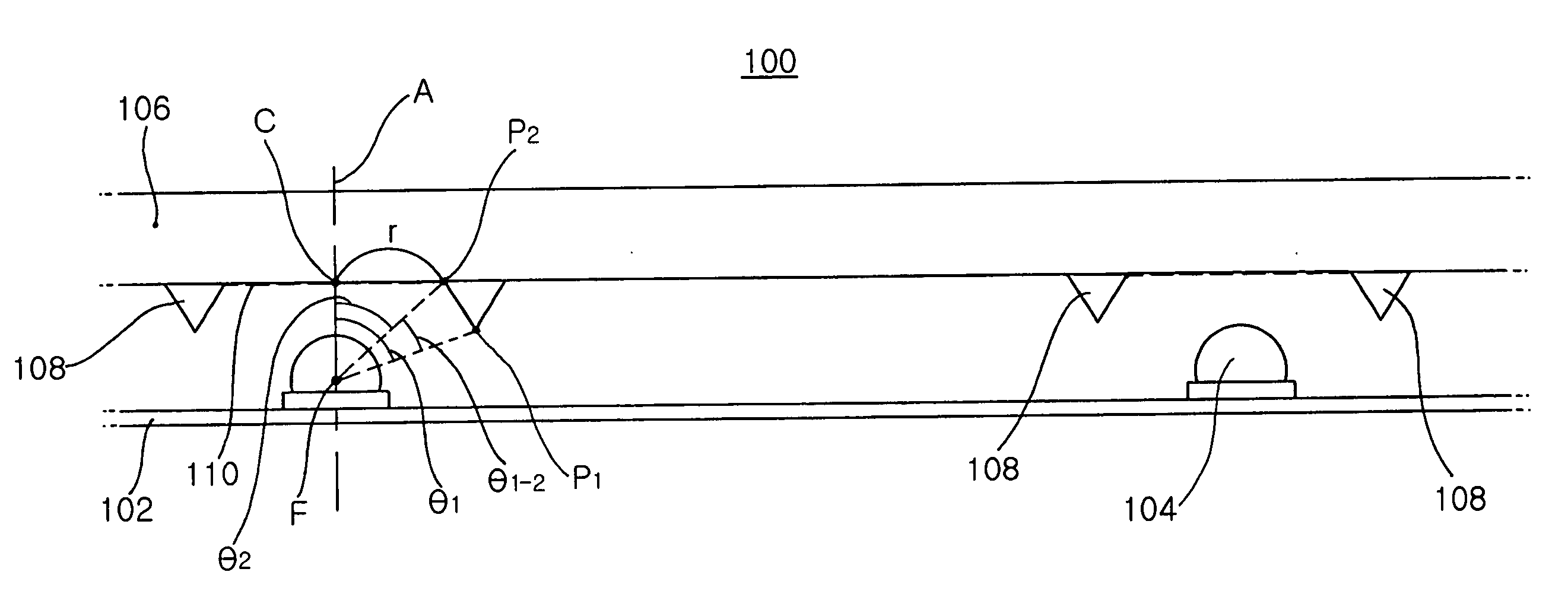
[0036]FIG. 3 is a schematic cross-sectional view of a direct-illumination backlight apparatus of the invention.

[0037] Referring to FIG. 3, the direct-illumination backlight apparatus 100 of the invention includes a flat reflective plate 102, a plurality of LED light sources 104 mounted on the reflective plate 102, a transparent plate 106 placed above the LED light sources 104, a plurality of scattering patterns 110 placed on the underside of the transparent plate 106 in positions opposed to the LED light sources 104 and transparent light-guide members 108 placed around the scattering patterns 110, respectively.

[0038] The reflective plate 102 is generally arranged in the form of a thin film or sheet on a base plate, and preferably has a Lambertian surface.

[0039] The LED light sources 104 are of monochromatic LEDs, and RGB LED light sources 104 are pref...


PUM


Abstract

A direct-illumination backlight apparatus uses LEDs as a light source. This backlight apparatus comprises: a flat reflective plate; an LED light source arranged on the reflective plate; a transparent plate arranged above the LED light source; a scattering pattern arranged on an underside of the transparent plate in a position corresponding to the LED light source; and a light guide made of transparent material, and arranged around the scattering pattern to introduce light incident from below into the transparent plate so that the light is internally reflected by the transparent plate. The light guide serves to introduce a partial light from an LED light source at such an angle that the partial light is trapped inside the transparent plate, and the scattering pattern serves to scatter the trapped light beam at a position directly above the LED light source so that the scattered light beam escapes out of the transparent plate toward an LCD panel. This can remove any dark area above the LED light source in the transparent plate and thus reduce the thickness of the direct-illumination backlight apparatus.

Description

CLAIM OF PRIORITY [0001] This application claims the benefit of Korean Patent Application No. 10-2005-0013659 filed on Feb. 18, 2005, in the Korean Intellectual Property Office, the disclosure of which is incorporated herein by reference. BACKGROUND OF THE INVENTION [0002] 1. Field of the Invention [0003] The present invention relates to a direct-illumination backlight apparatus using LEDs as a light source, more particularly, which is designed to introduce a partial light from an LED light source at such an angle that the partial light is trapped inside the transparent plate, and then scatter the trapped light beam at a position directly above the LED light source so that the scattered light beam escapes out of the transparent plate toward an LCD panel, thereby removing any dark area above the LED light source in the transparent plate and thus reducing its thickness. [0004] 2. Description of the Related Art [0005] Liquid crystal display (LCD) backlight apparatuses using LEDs illumi...

Claims


Application Information

Patent Timeline
IPC IPC(8): G01D11/28
CPCG02B6/0021G02B6/0038G02B6/0041G02F1/133603A01G9/246
Inventor KIM, HYUNG SUKPARK, JUNG KYUAHN, HO SIKJEONG, YOUNG JUNEPARK, YOUNG SAMHAHM, HUN JOOKIM, BUM JIN
Owner SAMSUNG ELECTRONICS CO LTD
Why Eureka
Try Eureka