
Light-duide plate and backlight module

a technology of light-duide plate and backlight module, which is applied in the direction of lighting and heating apparatus, instruments, optical elements, etc., can solve the problems of deteriorating light transmission efficiency, thin display devices, and higher thickness of direct-type backlight modules, and achieve the effect of high light transmission efficiency

Active Publication Date: 2006-08-24
CPT TECH GRP
View PDF5 Cites 7 Cited by
  • Summary
  • Abstract
  • Description
  • Claims
  • Application Information

AI Technical Summary

Benefits of technology

[0007] Accordingly, the present invention is directed to a light-guide plate for improving light transmission efficiency.
[0010] The light-guide board and the light-guide part buried inside the light-guide board have different refractive index so that the total reflection may occur for improving the light transmission efficiency in the light-guide plate.
[0012] The backlight module of the present invention has the light-guide plate having high light transmission efficiency so that the backlight module can be applied to large size LCD devices.

Problems solved by technology

However, the direct type backlight module has a higher thickness, which is disadvantageous for application in thin display devices.
If the light transmitted in the light-guide plate has higher energy loss or does not transmit out from the light-guide plate, it may deteriorate the light transmission efficiency.

Method used


Image

  • Light-duide plate and backlight module
  • Light-duide plate and backlight module
  • Light-duide plate and backlight module

Examples


Embodiment Construction

[0019] Reference will now be made in detail to the present preferred embodiments of the invention, examples of which are illustrated in the accompanying drawings. Wherever possible, the same reference numbers are used in the drawings and the description to refer to the same or like parts.

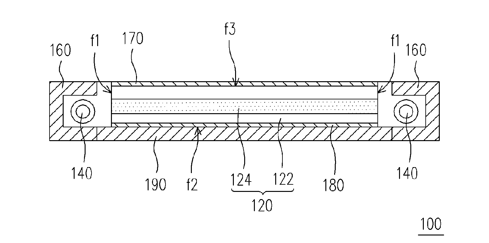
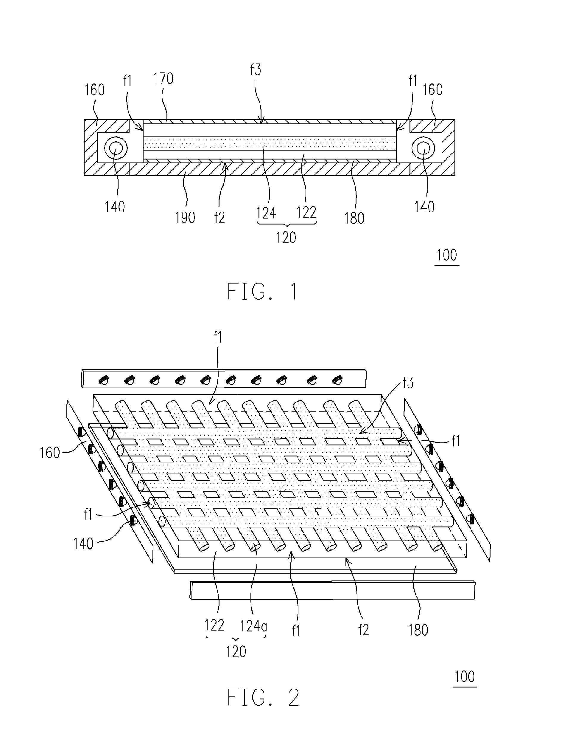
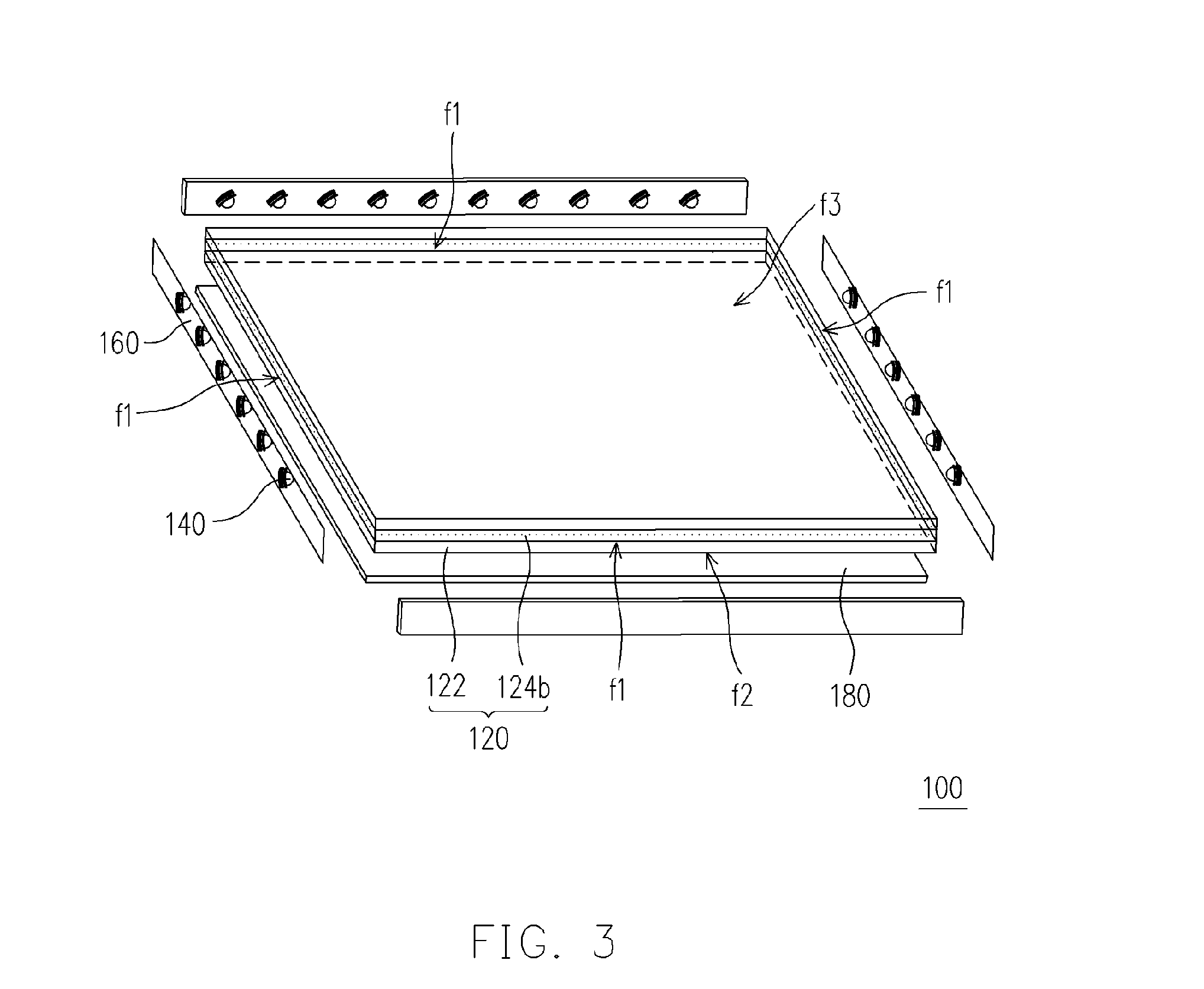
[0020]FIG. 1 is a schematic cross-sectional view showing an edge type backlight module according to an embodiment of the invention. The edge type backlight module 100 comprises at least a light-guide plate 120 and a light source 140. In an embodiment, the backlight module 100 further comprises a reflective cover 160, at least one optical film 170, a reflective film 180 and a frame 190.

[0021] As shown in FIG. 1, the light-guide plate 120 further comprises a light-guide board 122 and at least one light-guide part 124 buried inside the light-guide board 122. Preferably, the light-guide part 124 is uniformly buried inside the light-guide board 122. The light-guide board 122 has a first reflective inde...


PUM


Abstract

A light-guide plate comprising a light-guide board having a first refractive index and at least one light-guide part buried inside the light-guide board is provided. The light-guide part has a second refractive index larger than the first refractive index. The light-guide board and the light-guide part buried therein have different refractive indices so that the total reflection may occur for improving the light transmission efficiency in the light-guide plate.

Description

BACKGROUND OF THE INVENTION [0001] 1. Field of the Invention [0002] The present invention generally relates to a light-guide plate and a backlight module. More particularly, the present invention relates to a light-guide plate and a backlight module capable of improving the light transmission efficiency. [0003] 2. Description of Related Art [0004] With recent advancement in opto-electronic fabricating techniques, the development of flat panel display devices such as liquid crystal display (LCD), organic light emitting diode (OLED) and plasma display panel (PDP) have proceeded quite rapidly. Especially, the liquid crystal display has been widely applied to cell phones, notebooks, personal computers, personal digital assistant (PDA) and the like. [0005] For a liquid crystal display device, a backlight module is needed to provide the surface light source for the liquid crystal panel. Generally, the backlight module may be a direct type backlight module or an edge type backlight module....

Claims


Application Information

Patent Timeline
IPC IPC(8): F21V7/04
CPCG02B6/0023G02B6/0041
Inventor TSENG, WEI-YANGTING, CHU-CHICHIU, TIEN-LUNGLO, WEI-YU
Owner CPT TECH GRP
Learn More