
Cochlear Stimulation Device

a cochlear stimulation and device technology, applied in the field of cochlear stimulation systems, can solve the problems of cumbersome and unsightly headpieces, overall cost and reliability of the system, and achieve the effects of improving reliability, reducing cost, and improving cosmetics

Inactive Publication Date: 2006-08-24
ADVNACED BIONICS LLC
View PDF8 Cites 66 Cited by
  • Summary
  • Abstract
  • Description
  • Claims
  • Application Information

AI Technical Summary

Benefits of technology

[0049] Various advantages are potentially achieved through use of the present invention. These advantages include, but are not limited to, reduced cost, improved cosmetics, improved reliability, elimination of the headpiece, a smaller-sized implant unit which requires no magnet, a reduced incision size during surgery when implanting the implanted portion, a carrier signal having a frequency legally allowed by regulatory agencies, and improved performance. In various embodiments, a fully implantable one-piece system may last up to 20 years or more.

Problems solved by technology

Disadvantageously, the headpiece, although small, is sometimes viewed as cumbersome and unsightly.
Further, because the headpiece coil is usually held in place magnetically, the magnetic forces can sometimes prove uncomfortable, i.e., too strong, or cause physical irritation requiring intervention, so spacers or other means must be utilized to find a magnetic force that is sufficiently strong to hold the headpiece in place, yet not so strong as to be uncomfortable.
Additionally, the presence of the magnet within the implant portion of the system may prevent or potentially interfere with desired or needed medical procedures, e.g., Magnetic Resonance Imaging (MRI).
Further, the headpiece, with its accompanying cable that connects the headpiece to the external circuitry, and the magnet, or other material that is attracted to the implanted magnet, and the implanted magnet used in the implant portion of the system, all represent separate parts of the cochlear implant system which contribute in a significant way to the overall cost and reliability of the system.

Method used


Image

  • Cochlear Stimulation Device
  • Cochlear Stimulation Device
  • Cochlear Stimulation Device

Examples


Embodiment Construction

[0073] The following description is of the best mode presently contemplated for carrying out the invention. This description is not to be taken in a limiting sense, but is made merely for the purpose of describing the general principles of the invention. The scope of the invention should be determined with reference to the claims.

[0074] The following U.S. patents and U.S. Publication teach various features and elements and systems that may be used with a cochlear implant system embodying the present invention. Each of the listed U.S. patents or U.S. Publication is incorporated herein by reference: U.S. Pat. Nos. 5,584,869; 6,181,969; 6,212,431, 6,219,580; 6,272,382; 6,308,101; 6,505,076; and Pub. No. 2003 / 0031336 A1.

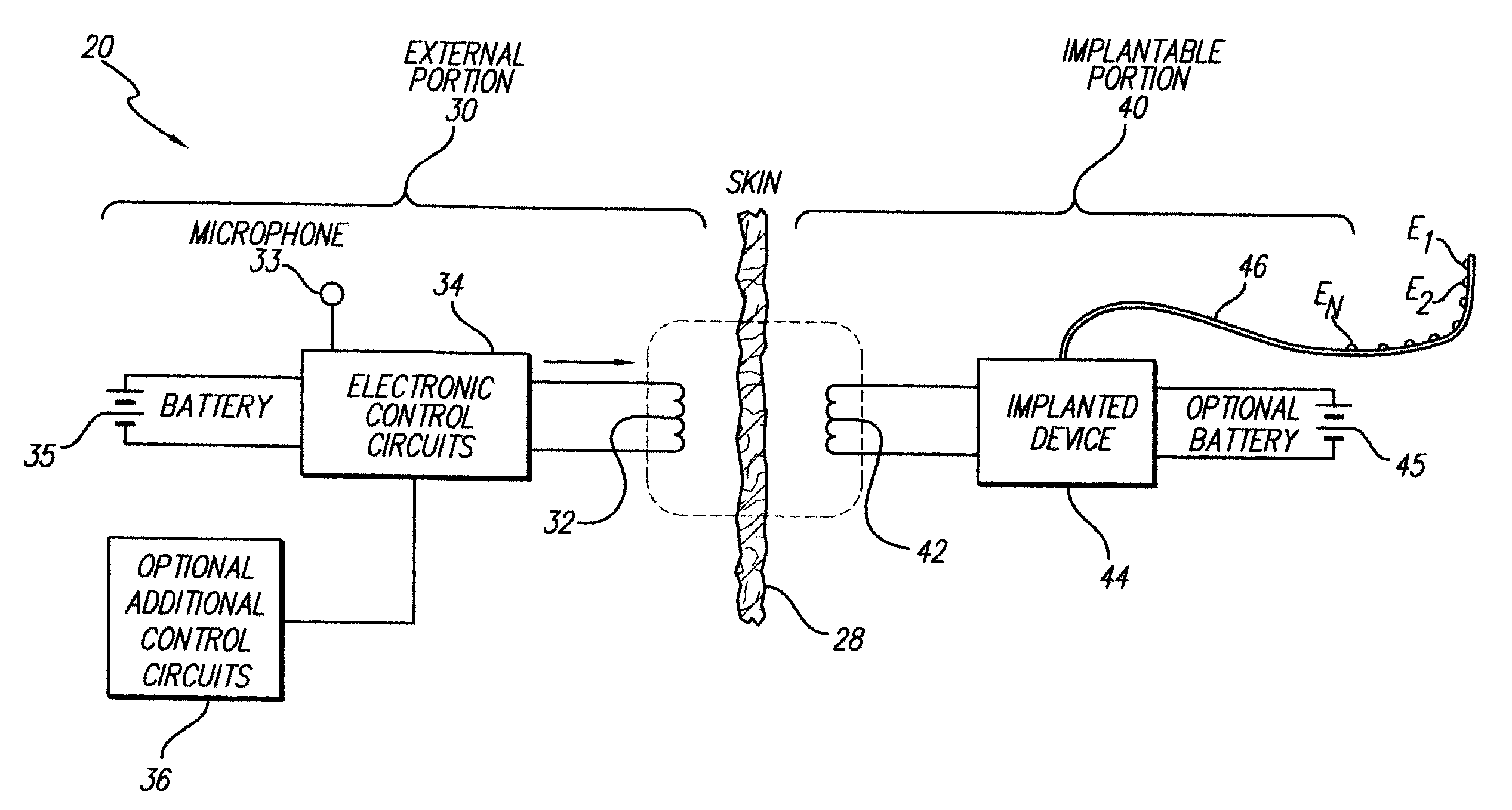
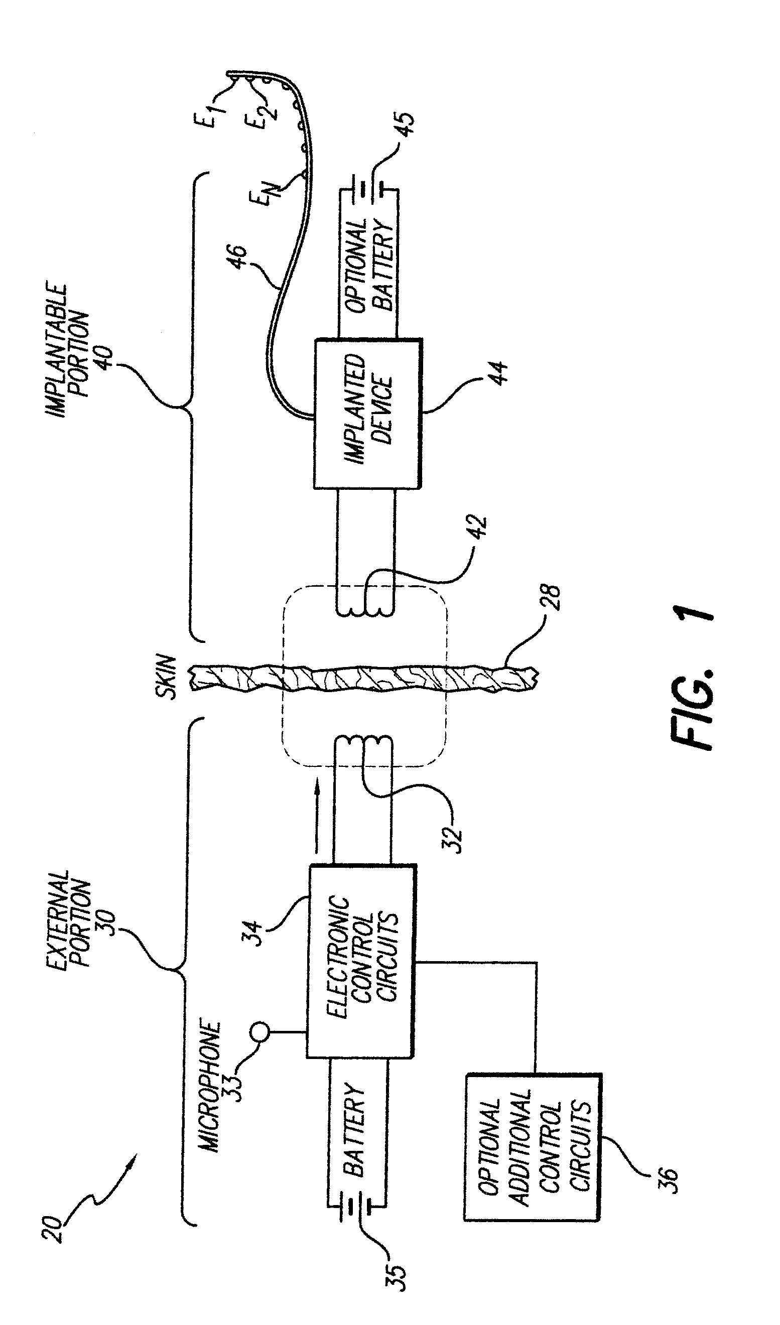
[0075]FIG. 1 shows an implantable stimulation system 20, e.g., an implantable cochlear stimulation system, according to an example embodiment of the present invention. The system 20 includes an external portion 30 and an implantable portion 40. In this example embodime...


PUM


Abstract

A cochlear stimulation apparatus includes an implantable device and an external device. The implantable device includes a receiving coil, an array of electrodes configured to be fitted within the cochlea of a user, and circuitry for receiving signals through the receiving coil and generating stimulation pulses that are directed to selected electrodes of the array. The external device is in the form of a single, integral unit. The external device includes circuitry for processing sensed sound information to generate the signals, a transfer coil for transferring the signals to the receiving coil and a ferromagnetic core for providing a low reluctance path between the transfer coil and the receiving coil.

Description

CROSS-REFERENCE TO RELATED APPLICATIONS [0001] This application is a continuation-in-part of U.S. patent application Ser. No. 11 / 124,495, filed on May 5, 2005, which claims the benefit of U.S. Provisional Application No. 60 / 568,957, filed on May 7, 2004, which application is incorporated herein by reference.FIELD OF THE INVENTION [0002] The present invention relates to cochlear stimulation systems, and more particularly to a cochlear stimulation system that does not require a headpiece or an implanted magnet and that improves inductive coupling between external and internal coil components of the cochlear stimulation system. BACKGROUND OF THE INVENTION [0003] Current cochlear implant systems include an implant portion and an external portion. The implant portion typically includes: (1) an electrode array, (2) an implanted coil, and (3) a hermetically-sealed housing to which the electrode array and implanted coil are attached and in which electronic circuitry, e.g., data processing c...

Claims


Application Information

Patent Timeline
IPC IPC(8): A61N1/18
CPCA61N1/0541A61N1/36032A61N1/37229A61N1/36038
Inventor GRIFFITH, GLEN A.
Owner ADVNACED BIONICS LLC
Learn More