Emulation processor interconnection architecture

a technology of interconnection and processor, applied in the direction of cad circuit design, program control, instruments, etc., can solve the problems of reducing operating speed, increasing the number of emulation processors required to efficiently verify the design, and consuming to fabricate the design into silicon, so as to reduce the amount of area, interconnection and power dedicated, and improve the efficiency of the design verification system.

Active Publication Date: 2006-08-24
CADENCE DESIGN SYST INC
View PDF1 Cites 9 Cited by
  • Summary
  • Abstract
  • Description
  • Claims
  • Application Information

AI Technical Summary

Benefits of technology

The patent text describes a method to reduce the size of a computer chip by eliminating certain components. This results in faster processing times and increased efficiency of the chip design verification system.

Problems solved by technology

The technical problem addressed in this patent text is the increasing number of processors and interconnect required for processor-based design verification systems, which can lead to a severe increase in area and power required by the system. The patent text proposes a solution to interconnecting emulation processors within a processor-based design verification system without increasing the required chip area and power.

Method used


Image

  • Emulation processor interconnection architecture
  • Emulation processor interconnection architecture
  • Emulation processor interconnection architecture

Examples


Embodiment Construction

[0028] With reference to the figures, the presently disclosed hardware design verification system and methods for the same will be discussed herein.

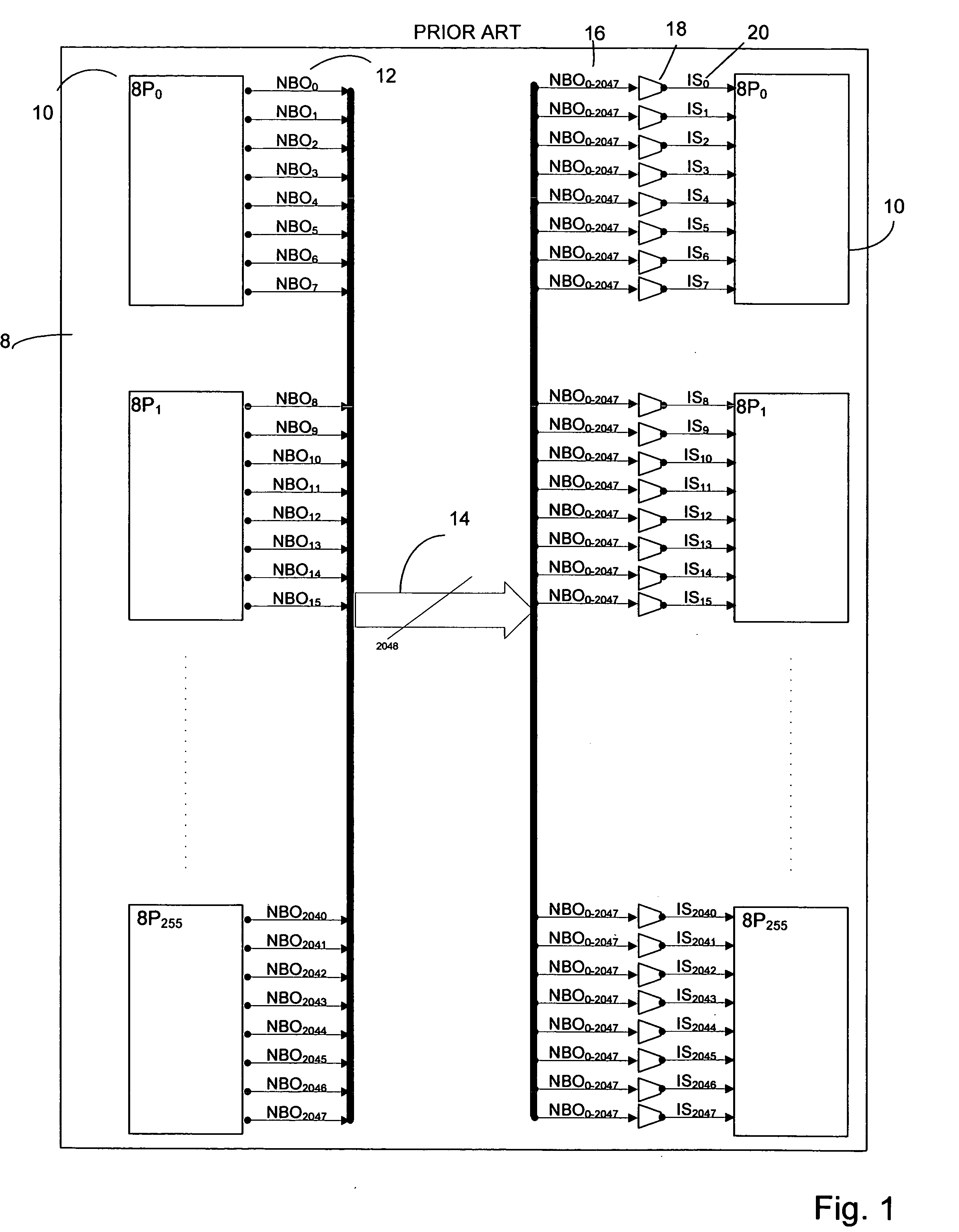
[0029]FIG. 1 depicts a prior art hardware design verification system 8 implementing 2,048 emulation processors according to the current state of the art. A number of emulation clusters 10 make up the system. The emulation clusters 10 are interconnected by signal busses 14, 16 and multiplexers 18. Each cluster outputs a number of node bit outs (NBO) 12 for a total of 2,048 NBOs. Each of the 2,048 NBOs meet to form a first NBO bus 14. The first NBO bus 14 carrying all 2,048 bits is then passed into the multiplexers 18 on signal busses 16. The multiplexers 18 select one of the 2,048 signals and output IS signal 20, which is passed back into each emulation cluster 10. Thus, each bus 16 carries all 2,048 NBOs as inputs to each of the multiplexers 18, which select a signal for input to the emulation clusters 10.

[0030] It should be noted with...


PUM


Abstract

The present system and methods are directed to the interconnection of clusters of emulation processors comprising emulation processors in a software-driven hardware design verification system. The processors each output one NBO output signal. The clusters are interconnected by partitioning a common NBO bus into a number of smaller NBO busses, each carrying unique NBO signals but together carrying every NBO. Each of the smaller NBO busses are passed into a series of multiplexers, each dedicated to a particular processor. The multiplexers select a signal for output back to the emulation clusters. The multiplexers that handle these smaller NBO busses are narrower than was previously required, thus reducing the amount of power, interconnect, and area required by the multiplexer array and dedicated interconnect.

Description


Claims


Application Information

Patent Timeline
Owner CADENCE DESIGN SYST INC
Why Eureka
Try Eureka