Near-transparent or transparent multi-channel encoder/decoder scheme

a multi-channel encoder and decoder technology, applied in frequency-division multiplexes, data switching networks, instruments, etc., can solve the problems of time delay, limited parametric methods, and loss of m/s coding gain, so as to reduce redundancy in residual signals and reduce processing power. efficiency, the effect of reducing the redundancy

Active Publication Date: 2006-08-24
FRAUNHOFER GESELLSCHAFT ZUR FOERDERUNG DER ANGEWANDTEN FORSCHUNG EV
View PDF4 Cites 330 Cited by
  • Summary
  • Abstract
  • Description
  • Claims
  • Application Information

AI Technical Summary

Benefits of technology

[0012] It is the object of the present invention to provide an encoding / decoding scheme allowing increased quality and reduced bitrate compared to existing multi channel encoding schemes.
[0020] The inventive encoding / decoding scheme is advantageous in that it is able to move seamlessly from pure parametric encoding to waveform-approximating or perfect waveform-transparent coding.
[0021] Preferably, parametric stereo coding and Mid / Side stereo coding are combined into a scheme that has the ability to converge towards transparent quality. In this preferred Mid / Side stereo-related scheme, the correlation between the signal components, i.e., the left channel and the right channel are more efficiently exploited.
[0026] The above-mentioned embodiment allows high flexibility for scalably encoding the residual signal. It is, however, quite processing-power demanding, since a complete multi channel reconstruction is performed at the encoder and an error representation for each channel of the multi channel signal is to be generated and input into the residual processor. On the decoder-side, it is necessary to firstly calculate the first reconstructed multi channel signal and then, based on the decoded residual signal, which is any representation of the error signal, the second reconstructed signal has to be generated. Thus, irrespective of the fact, whether the first reconstructed signal is to be output or not, it has to be calculated on the decoder-side.
[0028] This scheme is very efficient on the encoder and decoder sides. When the residual signal is not transmitted or has been stripped off from a scaleable data stream because of bandwidth requirements, the inventive decoder automatically generates a first reconstructed multi channel signal based on the down-mix channel and the gain and alignment parameters, while, when a residual signal not equal to zero is input, the multi channel reconstructor does not calculate the first reconstructed multi channel signal, but only calculates the second reconstructed multi channel signal. Thus, this encoder / decoder scheme is advantageous in that it allows for a quite efficient calculation on the encoder side as well as the decoder side, and uses the parameter representation for reducing the redundancy in the residual signal so that a very processing power-efficient and bitrate-efficient encoding / decoding scheme is obtained.

Problems solved by technology

A problem with the M / S approach towards redundancy exploitation, is that if the two components are out of phase (one is delayed relative the other), the M / S coding gain vanishes.
This is a conceptual problem, since time delays are frequent in real audio signals.
In audio recordings, time delays may stem from both stereophonic microphone setups, and from artificial post processing (sound effects).
However, parametric methods are limited in the sense that at higher bit rates, the coders are not able to reach transparent quality due to the inherent modeling constraint.
The problems related to parametric multi channel encoders are that their maximum obtainable quality value is limited to a threshold, which is significantly below the transparent quality.
This means that even with an increased bitrate, the quality of such a parametric multi channel encoder cannot increase anymore.

Method used


Image

  • Near-transparent or transparent multi-channel encoder/decoder scheme
  • Near-transparent or transparent multi-channel encoder/decoder scheme
  • Near-transparent or transparent multi-channel encoder/decoder scheme

Examples


Embodiment Construction

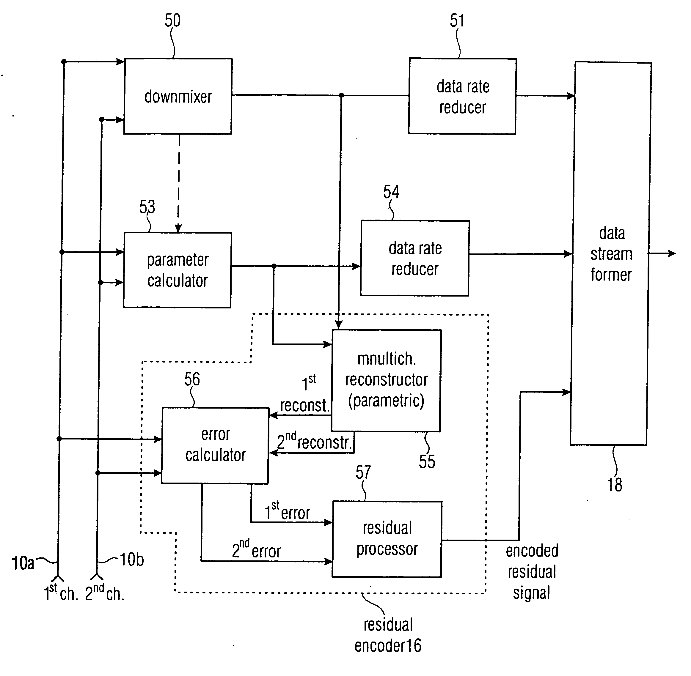
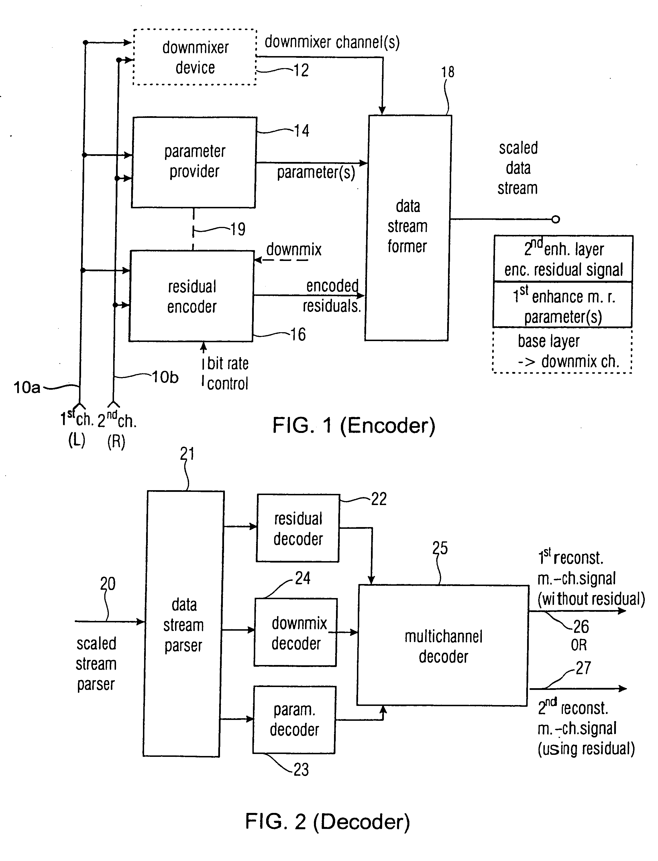
[0044]FIG. 1 shows a preferred embodiment of a multi channel encoder for encoding an original multi channel signal having at least two channels. The first channel may be a left channel 10a, and the second channel may be a right channel 10b in a stereo environment. Although the inventive embodiments are described in the context of a stereo scheme, the extension to a multi channel scheme is straight-forward, since a multi channel representation having for example five channels has several pairs of a first channel and a second channel. In the context of a 5.1 surround scheme, the first channel can be the front left channel, and the second channel can be the front right channel. Alternatively, the first channel can be the front left channel, and the second channel can be the center channel. Alternatively, the first channel can be the center channel and the second channel can be the front right channel. Alternatively, the first channel can be the rear left channel (left surround channel)...


PUM


Abstract

A multi-channel encoder / decoder scheme additionally preferably generates a waveform-type residual signal. This residual signal is transmitted together with one or more multi-channel parameters to a decoder. In contrast to a purely parametric multi-channel decoder, the enhanced decoder generates a multi-channel output signal having an improved output quality because of the additional residual signal.

Description

CROSS-REFERENCE TO RELATED APPLICATION [0001] This application claims the benefit of U.S. provisional application No. 60 / 655,216, filed Feb. 22, 2005, the disclosure of which is incorporated herewith in its entirety.FIELD OF THE INVENTION [0002] The present invention relates to multi channel coding schemes and, in particular, to parametric multi channel coding schemes. BACKGROUND OF THE INVENTION AND PRIOR ART [0003] Today, two techniques dominate for exploiting the stereo redundancy and irrelevancy contained in stereophonic audio signals. Mid-Side (M / S) stereo coding [1], primarily aims at redundancy removal, and is based on the fact that since the two channels are often fairly correlated, it is better to encode the sum, and the difference between the two. More bits (relatively) can then be spent on the high power sum signal, than on the low power side (or difference) signal. Intensity stereo coding [2, 3], on the other hand, achieves irrelevancy removal by, in each subband, replac...

Claims


Application Information

Patent Timeline
Patent Type & Authority Applications(United States)
IPC IPC(8): G10L19/00
CPCG10L19/008H04S3/008H04S2420/03
Inventor LINDBLOM, JONAS
Owner FRAUNHOFER GESELLSCHAFT ZUR FOERDERUNG DER ANGEWANDTEN FORSCHUNG EV
Why Eureka
Try Eureka