Ultrasonic washing device

a washing device and ultrasonic technology, applied in the direction of cleaning using liquids, physical therapy, chemistry apparatus and processes, etc., can solve the problems of misty washing and lack of deterrence, and achieve the effect of reducing energy loss, ensuring deterrence, and increasing the efficiency of ultrasonic vibration propagation

Inactive Publication Date: 2006-08-31
MATSUSHITA ELECTRIC WORKS LTD
View PDF17 Cites 50 Cited by
  • Summary
  • Abstract
  • Description
  • Claims
  • Application Information

AI Technical Summary

Benefits of technology

[0009] According to such a configuration, the ultrasonic vibration generated by the ultrasonic transducer is propagated to the washing through only the ultrasonic wave propagation member, so that energy loss becomes smaller and the efficiency of propagation of the ultrasonic vibration becomes higher. Thus, even when an output power of the ultrasonic transducer is made smaller in comparison with the conventional ultrasonic washer, enough detergency can be obtained. Theref...

Problems solved by technology

On the other hand, when the output power of the ultrasonic transducer 522 is made too high, there is a ...

Method used


Image

  • Ultrasonic washing device
  • Ultrasonic washing device
  • Ultrasonic washing device

Examples


first embodiment

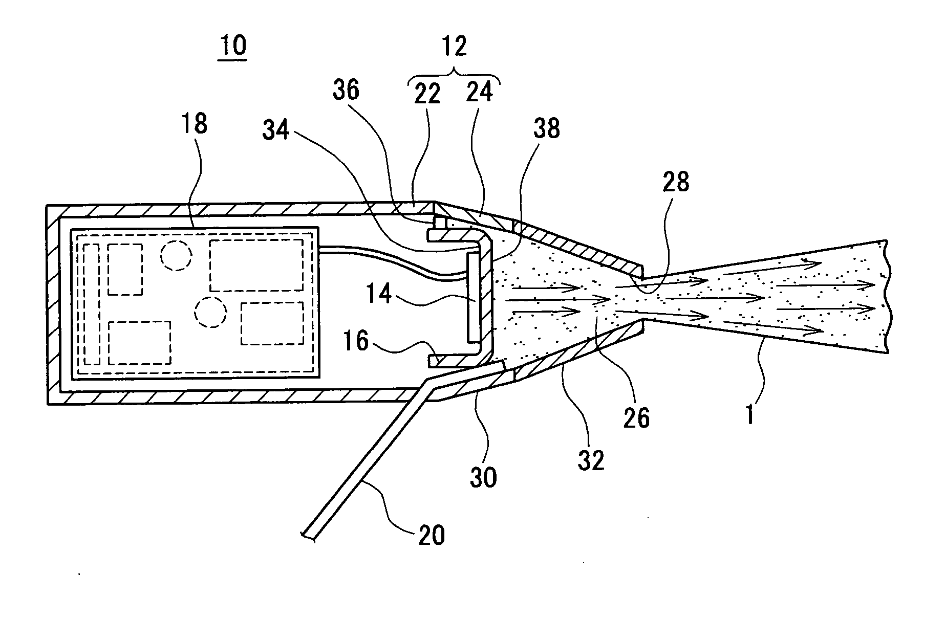
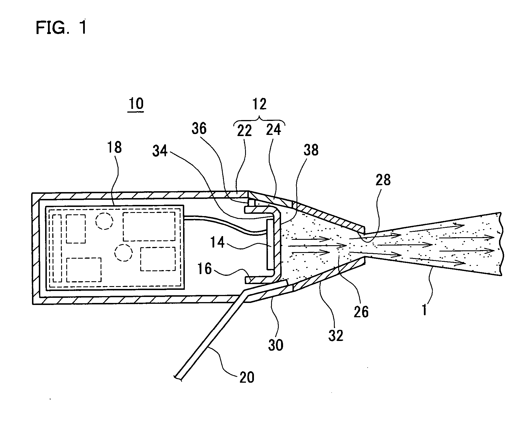
[0047] A configuration of an ultrasonic washer 10 in accordance with in a first embodiment of the present invention is shown in FIG. 1. The ultrasonic washer 10 comprises a housing 12 formed of an insulative synthetic resin. An ultrasonic transducer 14, an ultrasonic wave propagation member 16 to which the ultrasonic transducer 14 is joined, a driving circuit 18 for driving the ultrasonic transducer 14, and so on are provided in an inside of the housing 12.

[0048] The housing 12 is comprised of a substantially tube shaped main body 22, a nozzle unit 24 coupled with an end of the main body 22, and so on. A water supply pipe 20 is connected to the nozzle unit 24, so that washing is supplied to a cavity 26 of the nozzle unit 24 from a washing tank which is not illustrated. The nozzle unit 24 has, for example, a frustum shape, and is formed so that the cross-sectional area thereof becomes smaller as approaching to a front end of the housing 12. Furthermore, a front end of the nozzle uni...

second embodiment

[0060] Subsequently, a configuration of an ultrasonic washer 10 in accordance with a second embodiment of the present invention is shown in FIG. 4. Besides, with respect to the portions substantially the same as those in the above first and second (SIC) embodiments, description of them is omitted, and only dissimilarity is described.

[0061] As shown in FIG. 4, in the ultrasonic washer 10 in accordance with in the second embodiment, the ultrasonic wave propagation member 16 is substantially frustum shape, and a portion protruding into the cavity 26 of the nozzle unit 24 is formed so that the cross-sectional area of it in a direction parallel to a joint face with the ultrasonic transducer 14 becomes gradually smaller as approaching to the end portion of the nozzle, that is, an ultrasonic wave emission face 16A. Furthermore, the shape of the nozzle unit 24 is formed substantially frustum so that the cross-sectional area of it becomes smaller as approaching to the splay opening 28. Ther...

third embodiment

[0083] Subsequently, an ultrasonic washer 10 in accordance with a third embodiment of the present invention is described. In the third embodiment, the ultrasonic washer 10 is constituted as cordless. Besides, with respect to the portions substantially the same as those in the above-mentioned embodiments, description of them is omitted, and only dissimilarity is described.

[0084] In the ultrasonic washer 10 shown in FIG. 21, a rechargeable battery 19 and a pump 46 are provided in an inside of the main body 22 of the housing 12, and a washing tank 48 for pooling the washing is detachably mounted on a rear portion of the main body 22. In this way, when the washing tank 48 is provided on the ultrasonic washer 10 in it and constituted as cordless, it is possible to provide an ultrasonic washer superior to the portability and operationality.

[0085]FIG. 22 shows a modified example comprising a waste fluid collecting function for collecting the waste washing 1 bounced from the object to be ...


PUM


Abstract

In an ultrasonic washer for washing by splaying washing toward an object to be washed or a portion to be washed from a front end of a nozzle, a part of an ultrasonic wave propagation member connected to an ultrasonic transducer is protruded into a cavity of the nozzle into which the washing is filled in order to propagate ultrasonic vibration generated by the ultrasonic transducer to the washing efficiently. Furthermore, the ultrasonic wave propagation member is formed so that a cross-sectional area becomes gradually smaller as approaching to the front end thereof, so that the ultrasonic vibration is converged to the end face of the ultrasonic wave propagation member. Still furthermore, a length of the ultrasonic transducer and the ultrasonic wave propagation member is made to be integral multiplication of a half-wavelength of ultrasonic standing wave oscillation, and the end face of the ultrasonic wave propagation member from which the ultrasonic wave is emitted to the washing is disposed at a position of antinode of the ultrasonic standing wave oscillation where the amplitude becomes the largest.

Description

TECHNICAL FIELD [0001] The present invention relates to a washer utilizing ultrasonic vibration, and especially relates to an ultrasonic washer for washing an object to be washed or a portion to be washed by spreading washing from a nozzle, to which vibration energy due to ultrasonic wave is propagated. BACKGROUND ART [0002] For example, in Japanese Laid-Open Patent Publication No. 6-218337, an ultrasonic washer 520 as shown in FIG. 37 is proposed for washing an object to be washed or a portion to be washed by spraying washing from a nozzle, to which vibration energy due to ultrasonic wave is applied. [0003] The conventional ultrasonic washer 520 is comprised of a driving circuit 521, an ultrasonic transducer 522 driven by the driving circuit 521, an ultrasonic wave propagation member 523 for propagating ultrasonic vibration generated by the ultrasonic transducer 522, a cone 524 connected to the ultrasonic wave propagation member 523, a nozzle 525 connected to the cone 524 and servi...

Claims


Application Information

Patent Timeline
IPC IPC(8): B08B3/12B08B3/00A47K7/04A47K7/08A61H35/00B05B17/06B08B3/02E03D9/08
CPCB05B17/0623B08B3/02A61C17/0202A61C17/0208A61C17/20B08B2203/0288A47K7/043B05B1/02B05B17/06B08B3/12
Inventor NUNOMURA, MAHITOKISHIMOTO, TAKASHI
Owner MATSUSHITA ELECTRIC WORKS LTD
Why Eureka
Try Eureka