
Laser scanner having analog digitizer with increased noise immunity

a scanner and analog technology, applied in the field of scanners, can solve problems such as distortion of photodiode analog signals, disastrous consequences for scanner decoders, and problems such as high noise conditions, and achieve the effect of reducing errors in decoding bar codes and high noise conditions

Inactive Publication Date: 2006-08-31
SYMBOL TECH INC
View PDF19 Cites 3 Cited by
  • Summary
  • Abstract
  • Description
  • Claims
  • Application Information

AI Technical Summary

Benefits of technology

This solution enhances the digitizer's noise immunity and improves decoding accuracy for noisy bar code signals, reducing the likelihood of misdecodes and ensuring accurate width calculations of bar code elements.

Problems solved by technology

Noise makes the digitization process problematic.
Noise can include optical noise such as ambient light, paper grain or speckle noise, printing defects.
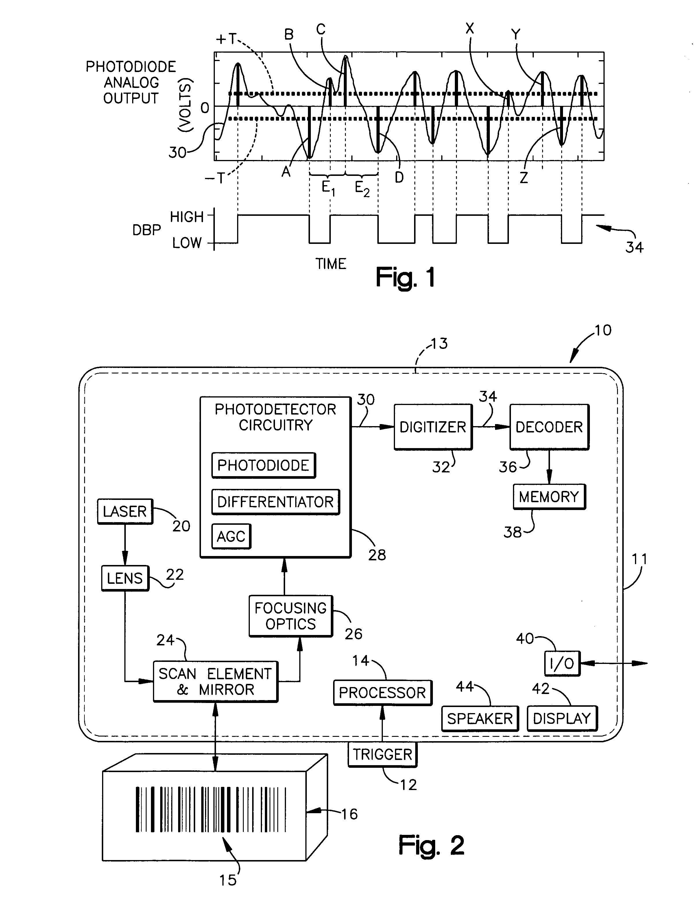
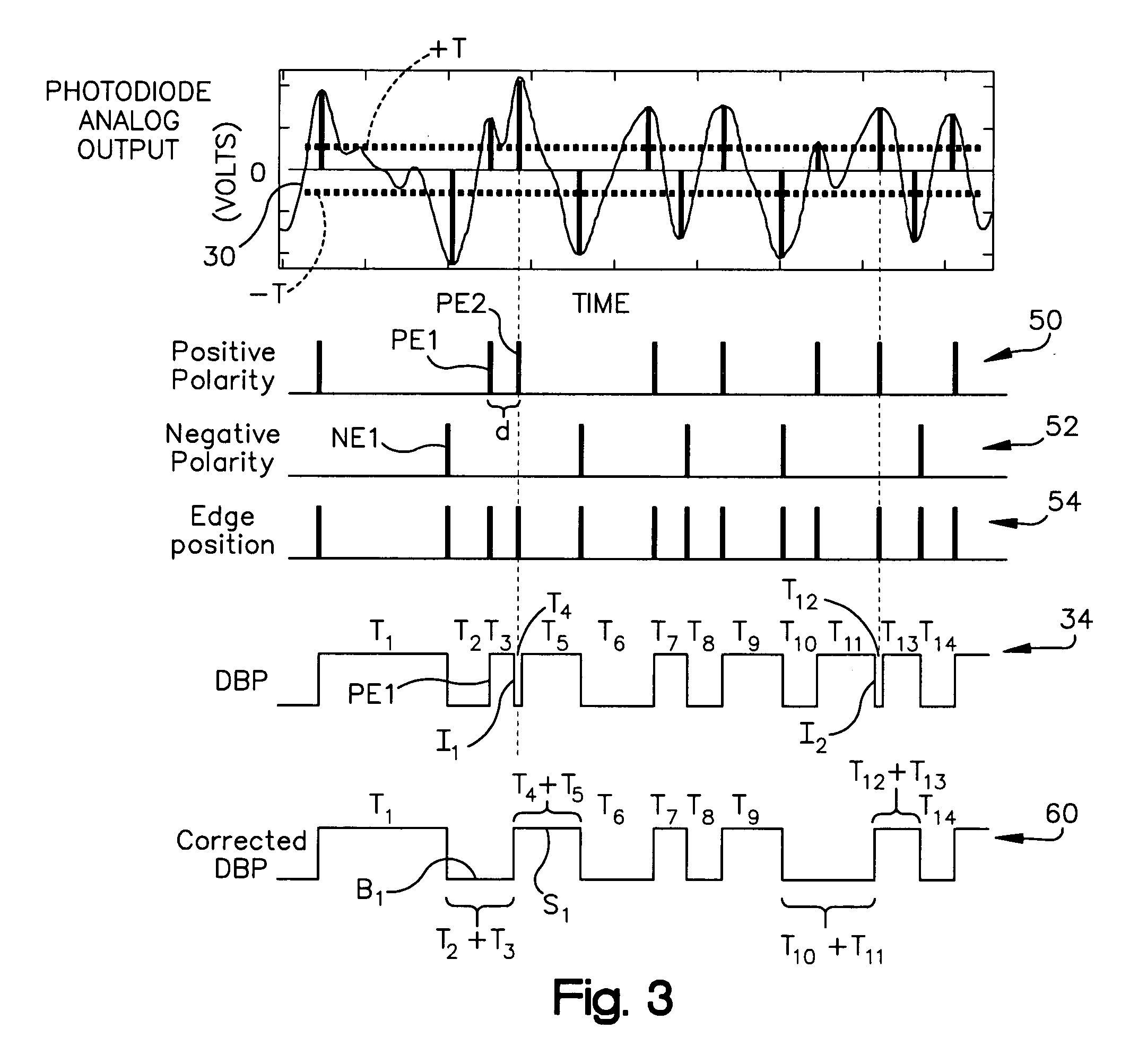
However, noise and the convolution effect of the laser beam may cause a distortion of the photodiode analog signal such that two or more consecutive edges of the signal may have the same polarity.
This has disastrous consequences for the scanner decoder.
In case of symbologies, which use all element combinations, like UPC such situation leads to character misclassification.
That results in a failure to decode, however if more than one such error occurs for a single symbol, then that may result in symbol misdecode.
The danger of misdecode is increased, if a symbol is decoded using fragments of a bar code coming from separate scans, like it is in case of block decoding or even more often in the case of half block stitching.

Method used


Image

  • Laser scanner having analog digitizer with increased noise immunity
  • Laser scanner having analog digitizer with increased noise immunity
  • Laser scanner having analog digitizer with increased noise immunity

Examples


Embodiment Construction

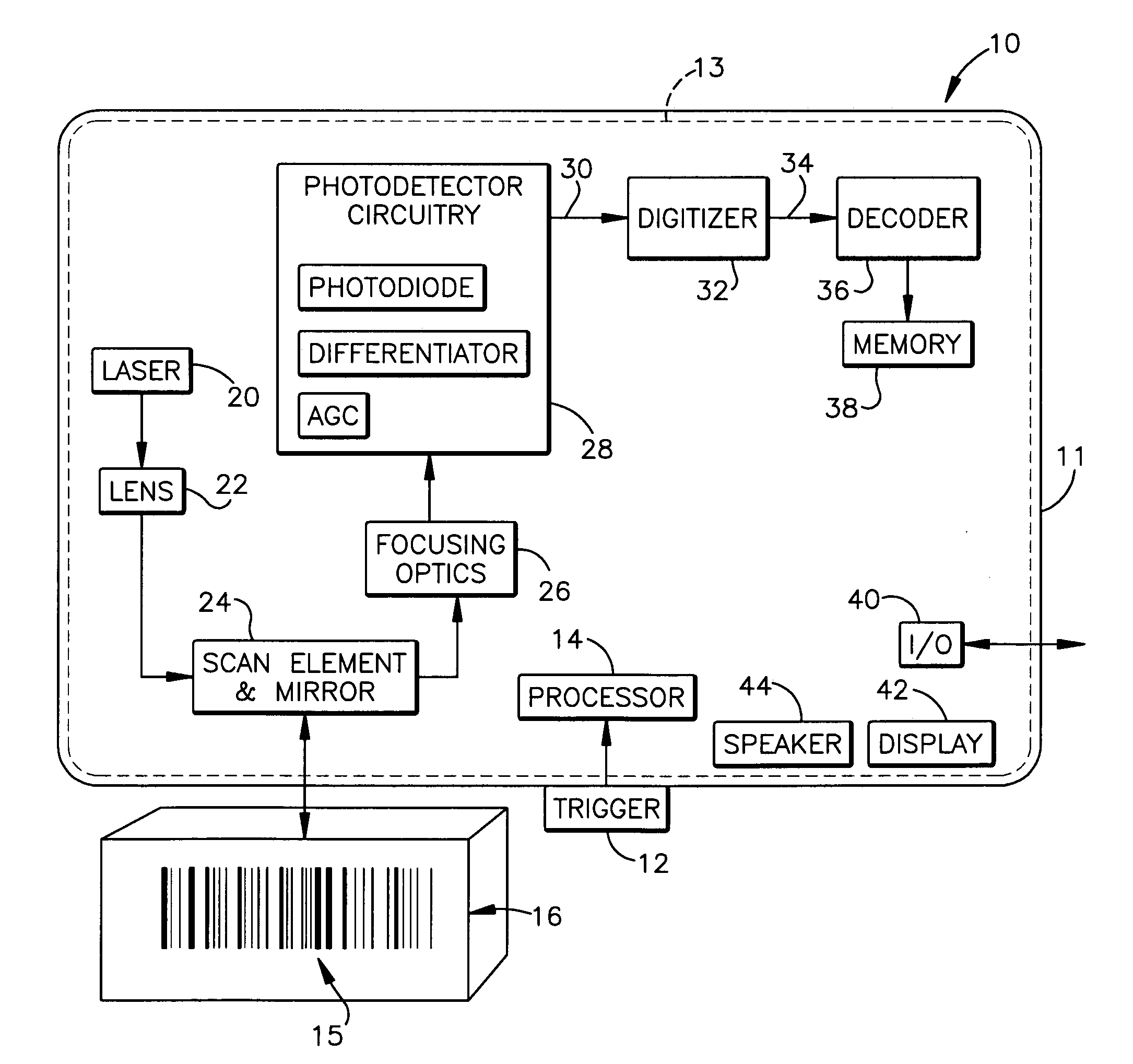
[0029] A laser scanner is shown schematically at 10 in FIG. 2. The bar code reader 10, in addition to reading (that is, scanning and decoding) both 1D and 2D bar codes and postal codes, is also capable of capturing images and signatures. In one preferred embodiment of the present invention, the laser scanner 10 is a hand held portable reader supported in a housing 11 that can be carried and used by a user walking or riding through a store, warehouse or plant for reading bar codes for stocking and inventory control purposes.

[0030] However, it should be recognized that digitizing and decoding system of the present invention, to be explained below, may be advantageously used in connection with any type of laser scanner, be it portable or stationary. It is the intent of the present invention to encompass all such laser scanners.

[0031] The bar code reader 10 includes a trigger 12 coupled to the bar code reader circuitry 13 operating under the control of a microprocessor 14 for reading ...


PUM


Abstract

A laser scanner for reading a bar code having a plurality of bar code elements. The laser scanner includes a digitizer which receives as an input an analog signal from photodetector circuitry and digitizes the analog signal to produce a digital bar code pattern (DBP) signal representative of the bar code. The DBP signal is input to a decoder which reads and decodes the DBP signal thereby decoding the bar code. The digitizer imposes a short duration correction impulse on the DBP signal whenever successive edges of the same polarity are sensed wherein both of the edges are above a threshold level and further wherein the second edge is of greater magnitude than the first edge. When a correction impulse is received on the DBP signal by the decoder, the decoder corrects the DBP signal by removing the first edge and toggling on the second edge.

Description

FIELD OF THE INVENTION [0001] The present invention relates to a laser scanner for reading bar codes and, more particularly, to a laser scanner having an analog digitizer with increased noise immunity. BACKGROUND OF THE INVENTION [0002] Laser scanners are widely used for reading bar codes, including one dimensional and two dimensional bar codes. In a laser scanner, a laser generates a beam, the beam is scanned or rapidly moved across a bar code or a portion of a bar code. Typically, the laser beam is focused by a lens and repetitively scanned by means of an oscillating or rotating mirror. Essentially, the beam generates a beam spot that moves across a target bar code. [0003] The space elements of the bar code reflect the laser beam illumination and the dark or black bar elements of the bar code absorb the laser beam. The reflected light from the bar code is focused by scanner light-receiving optics through a bandpass filter and onto a photodetector circuitry, such as a photodiode. T...

Claims


Application Information

Patent Timeline
Patent Type & Authority Applications(United States)
IPC IPC(8): G06K7/10
CPCG06K7/10851
Inventor MADEJ, DARIUSZ
Owner SYMBOL TECH INC
Learn More