Magnetic Fluidic Seal with Improved Pressure Capacity

a magnetic fluid and pressure capacity technology, applied in the direction of engine seals, shafts and bearings, bearing components, etc., can solve the problems of reducing the size of modern applications, the need for smaller magnetic fluid seals having the same pressure capacity, and the upper limit of the magnetic system, so as to reduce the choking effect, increase the pressure capacity of the seal, and increase the pressure capacity

Inactive Publication Date: 2006-08-31
LI ZHIXIN
View PDF4 Cites 15 Cited by
  • Summary
  • Abstract
  • Description
  • Claims
  • Application Information

AI Technical Summary

Benefits of technology

[0017] It is an object of the present invention to provide a multistage magnetic fluid seal having an increased pressure capacity. It is another object of the present invention to provide a multistage magnetic fluid seal having a geometric stage design that increases pressure capacity of the seal. It is a further object of the present invention to provide a multistage magnetic fluid seal having a geometric stage design that focuses the magnetic force field and decreases the choking effect. It is yet another object of the present invention to provide a multistage magnetic fluid seal having a geometric stage design that is less sensitive to axial misalignment than conventional multistage seals.
[0023] The trapezoidal-shaped stage solves the problems seen in the prior art, geometrically-shaped stage. Prior art geometrically-shaped stages are either acute triangle stages, equilateral triangle stages or rectangular stages. In each prior art triangle-shaped stage, the pointed tip of the triangular shape focuses the magnetic flux field. However, the pointed tip of the triangle causes choking of the magnetic flux field strength. A prior art rectangular stage, on the other hand, reduces the choking inherent with the pointed triangular stages. A drawback of the rectangular stage is that it does not focus the magnetic flux within the gap as well as the pointed tip of the triangular stages.
[0024] The trapezoidal-shaped stage of the present invention provides the benefits of reduced chocking of the rectangular-shaped stage with increased focusing of the magnetic flux field of the triangular-shaped stage. The trapezoidal-shaped stage provides an angled or tapered stage that focus the magnetic field better than the rectangular stage, while simultaneously reducing the effects of triangular stage choking by providing a flat, top portion on the opposing ridges of each stage. The trapezoidal-shaped stage of the present invention provides a multi-stage seal having higher pressure capacity than similar multi-stage seals utilizing rectangular-shaped or triangular-shaped stages.
[0025] In a multistage seal, making one of the ridges in each pair of opposing ridges wider than its opposing ridge also solves the problems seen in the prior art, geometrically-shaped stage. A wider ridge in a radially aligned and close non-contacting relationship with a narrower ridge reduces the choking of the rectangular-shaped stage of the prior art and increases the focusing of the magnetic flux field of that stage since the top flat portion is more tolerant to misalignment. Varying the width of the top of the ridge also reduces the leak field by decreasing the minimum magnetic flux density in between adjacent ridges.
[0026] The advantages of trapezoidal and / or varied width stages over prior art stages are even more greatly enhanced when seals with high pressure capacity must be designed. When seals with high pressure capacity are designed, stronger magnets are needed and used to generate strong magnetic fields. The stronger the magnet, the stronger and more dense the magnetic flux. At higher magnetic flux densities, the prior art rectangular-shaped stage begins to choke the magnetic flux more easily than the trapezoidal-shaped stage because the rectangular-shaped stage has higher resistance to magnetic flux. However, making one ridge in a pair of opposed ridges wider than its opposed ridge in a rectangular-shaped stage also provides similar benefits and advantages as those provided by the trapezoidal-shaped stage.
[0028] In this embodiment of the present invention, each of the plurality of opposed ring-like ridges of the second pole piece has the trapezoidal shape, one flat top portion wider than its opposing and facing top flat portion, or both. Like the previous embodiment, the double, opposed trapezoidal-shaped stage increases the pressure capacity of the stage even greater than the single trapezoidal-shaped stage. These increases are both significant and unexpected. In addition, the double trapezoidal-shaped stage as well as the stages having one flat top portion wider than its opposing and facing flat top portion also maintain a greater pressure capacity over a larger amount of stage offset, i.e. misalignment, compared to a similar triangular or rectangular-shaped double stage. This is very important in applications where double, opposed stages are used as stage offset occurs because various machining tolerances and assembling operations are involved.

Problems solved by technology

Conversely, as the size of modern applications decreases, smaller magnetic fluid seals having the same pressure capacity are also needed.
Thus, such a magnetic system has an upper limit and saturation develops at a relatively small number of teeth or ridges.
This is so because the magnetic flux field beneath each additional ridge is not strong and centrifugal forces easily throw the magnetic fluid away from the gap.
However, it is not always practical to simply increase the size of the magnetic seal.
Berkovsky further discloses that a seal with tapered teeth is disadvantageous since the structure must be fixed in both radial and axial directions.
Additionally, Berkovsky discloses that, since working gaps are small (about 0.2 millimeters), problems arise with serviceability of shafts and high shaft runout.
The eccentric location of the shaft and the poles due to high shaft runout causes changes in the working gap in the azimuthal direction, which causes magnetic field intensity changes in the gap between the shaft and the poles.
Even though the prior art knife edge stages help focus the magnetic flux lines in the air gap and thus slightly increase the differential pressure capacity, they also increase the magnetic choking effect with regard to the density of flux lines at the knife edges, which is limiting.
Where double, opposed knife edges are used, misalignment causes a decrease in the magnetic force field.

Method used


Image

  • Magnetic Fluidic Seal with Improved Pressure Capacity
  • Magnetic Fluidic Seal with Improved Pressure Capacity
  • Magnetic Fluidic Seal with Improved Pressure Capacity

Examples


Embodiment Construction

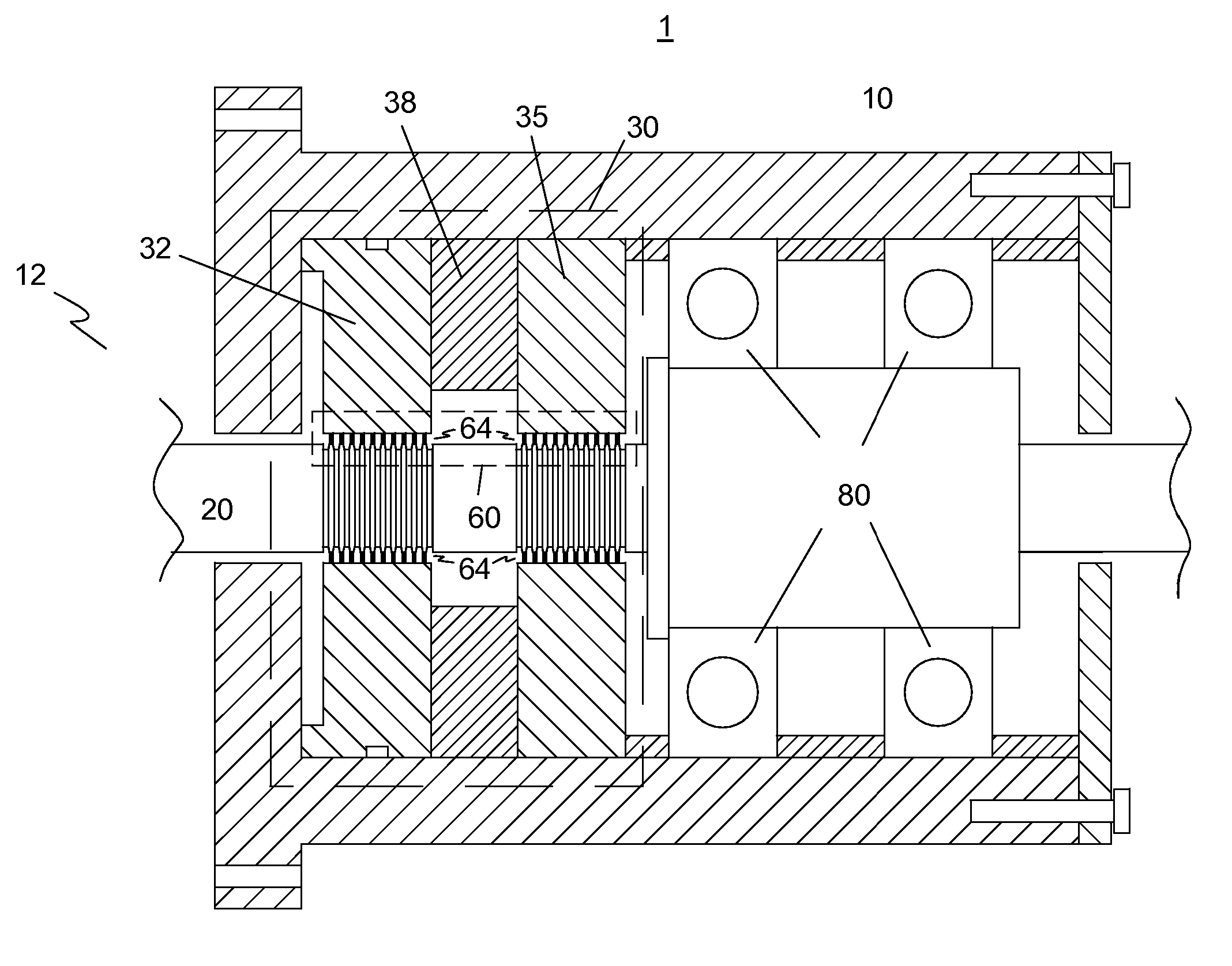
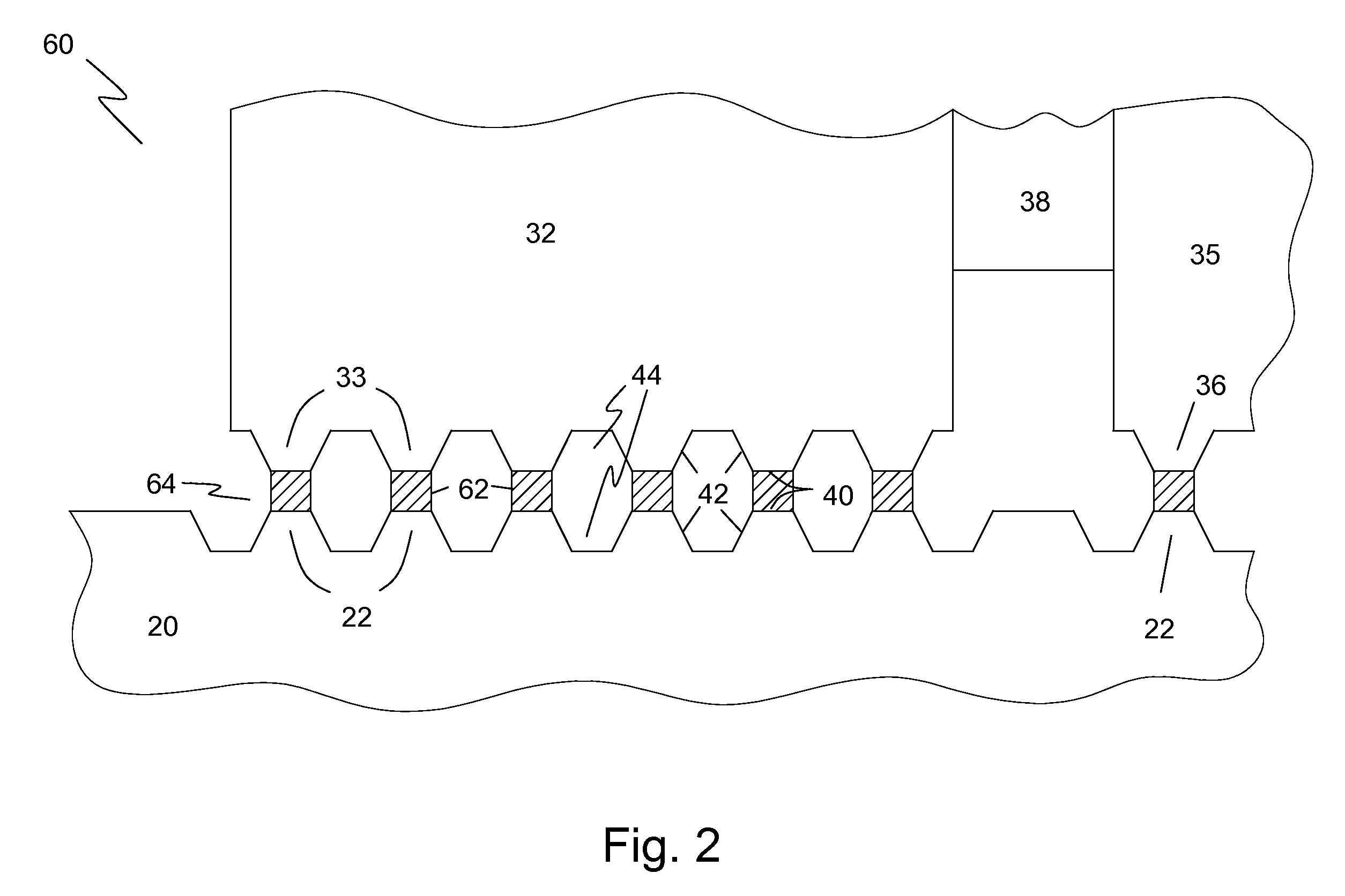
[0039] The preferred embodiment of the present invention is illustrated in FIGS. 1-3, 6, 8, and 9. FIG. 1 shows one embodiment of the present invention incorporated into a vacuum rotary seal 1. A rotary seal housing 10 supports a rotary shaft 20 that is inserted into a vacuum chamber 12. Rotary seal housing 10 is nonmagnetic and includes a ring-like magnetic assembly 30. Magnetic assembly 30 is adapted to have a multi-stage seal 60 between rotary seal housing 10 and the rotary shaft 20. Magnetic assembly 30 includes a first pole piece 32, a second pole piece 35 and a permanent magnet 38 between first pole piece 32 and second pole piece 35. First pole piece 32 and second pole piece 35 are magnetically permeable as is the rotary shaft 20. Rotary shaft 20 is supported by high-precision, lubricated rolling element bearings 80 to maintain concentricity within the inside diameter of magnetic assembly 30. A small radial gap, or annulus, 64 is created between rotary shaft 20 and first pole ...


PUM


Abstract

A magnetic assembly for a multistage magnetic fluid rotary seal has a shaft, an annular permanent magnet, at least one pole piece and a radial gap formed between the shaft and the pole piece. The shaft and the pole piece have a plurality of ridges in opposing, non-contacting relationship forming the radial gap. The ridges have a flat top portion facing the radial gap and each pair of facing flat top portions has one that is wider than the other.

Description

[0001] This application is a Continuation-in-Part application of Ser. No. 10 / 614,461 filed on Jul. 7, 2003.BACKGROUND OF THE INVENTION [0002] 1. Field of the Invention [0003] The present invention relates generally to magnetic fluid seals. Particularly, the present invention relates to multi-stage magnetic fluid seals. [0004] 2. Description of the Prior Art [0005] Magnetic fluid rotary seals have been widely used in vacuum applications over the past twenty years. The basic structure of the seal has at least one magnet, a rotary shaft, and pole pieces fastened within a housing. The magnet, the pole pieces and the shaft form a magnetic circuit with air gaps. A magnetic fluid is attracted to the air gap and forms the dynamic sealing between the pole pieces and the rotary shaft. The sealing between stationary parts such as between a pole and the housing is usually accomplished by using a rubber O-ring at the radial interface. Modern applications increasingly require magnetic fluid seals...

Claims


Application Information

Patent Timeline
Patent Type & Authority Applications(United States)
IPC IPC(8): F16J15/43
CPCF16C33/1035F16J15/43
Inventor LI, ZHIXIN
Owner LI ZHIXIN
Why Eureka
Try Eureka