Radio frequency identification of tagged articles

a radio frequency identification and article technology, applied in the direction of reradiation, indirect connection of subscribers, visible signalling systems, etc., can solve the problems of inability to teach, or even suggest, any rfid method and system possessing, above-prior art patents fail to teach, etc., to increase the probability of reading the codes, reduce the time of search, and increase the noise immunity

Inactive Publication Date: 2006-08-31
LEVIN EDUARD
View PDF11 Cites 35 Cited by
  • Summary
  • Abstract
  • Description
  • Claims
  • Application Information

AI Technical Summary

Benefits of technology

[0014] The invention possesses numerous benefits and advantages over known RFID systems. In particular, the invention permits the reduction of the time of search and recognition of tags when there are large numbers of tags to be recognized within an interrogation zone. It can locate each one of a plurality of objects and increases the probability of reading the codes without error. Noise immunity is increased due to the elimination of false responses when receiving signals are reflected from random surfaces such as the warehouse walls, shelves, adjacent articles, container surfaces, etc. One embodiment of the invention can be used with existing tags by providing only minor modifications of the input stages of the existing transponders. It may be used in a single-channel, or two-channel, or multi-channel systems. The universal character of the system allows it to be used as a mobile or a stationary device, as well as a two-dimensional or a three-dimensional space version.

Problems solved by technology

When a larger number of tags are to be read by the readers, tag signals reach the reader practically simultaneously, which may result in failure to recognize the objects with adequate accuracy.
All of the above prior art patents fail to teach, or even suggest, any RFID method and system possessing features which can perform a recognition and locating functions in case of a plurality of objects, and reading the codes and locating tags of both single decoding or working simultaneously with large numbers of articles, under conditions of locating the inventory objects on the plane or in the random volume with minimization of errors caused by reflection of signals from surrounding surfaces.

Method used


Image

  • Radio frequency identification of tagged articles
  • Radio frequency identification of tagged articles
  • Radio frequency identification of tagged articles

Examples


Embodiment Construction

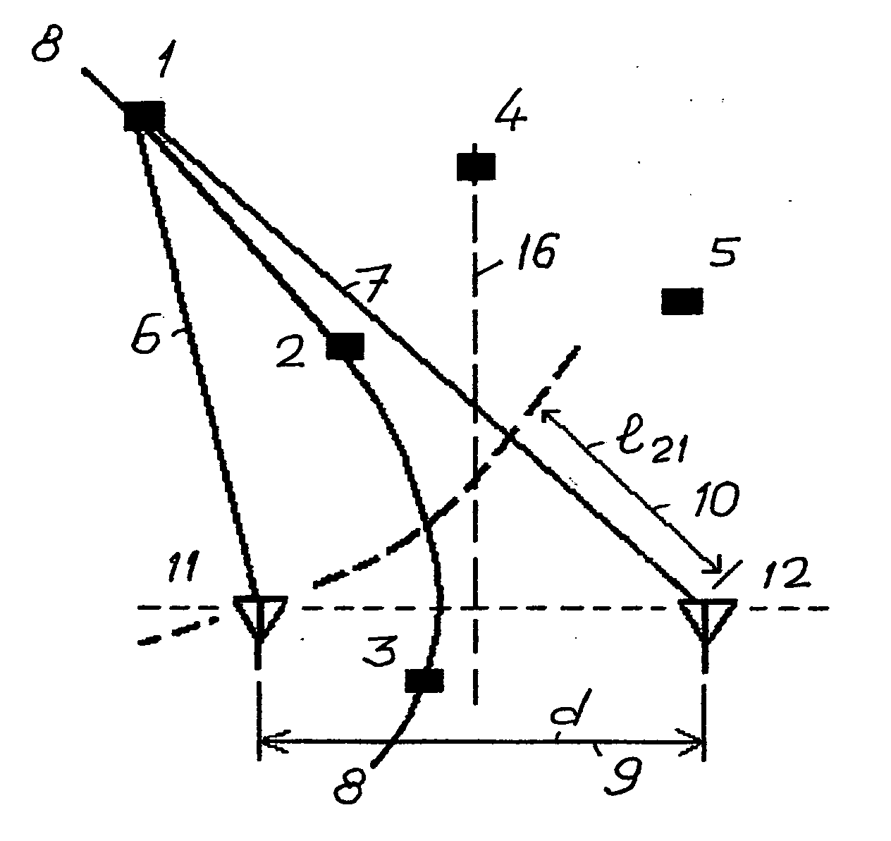
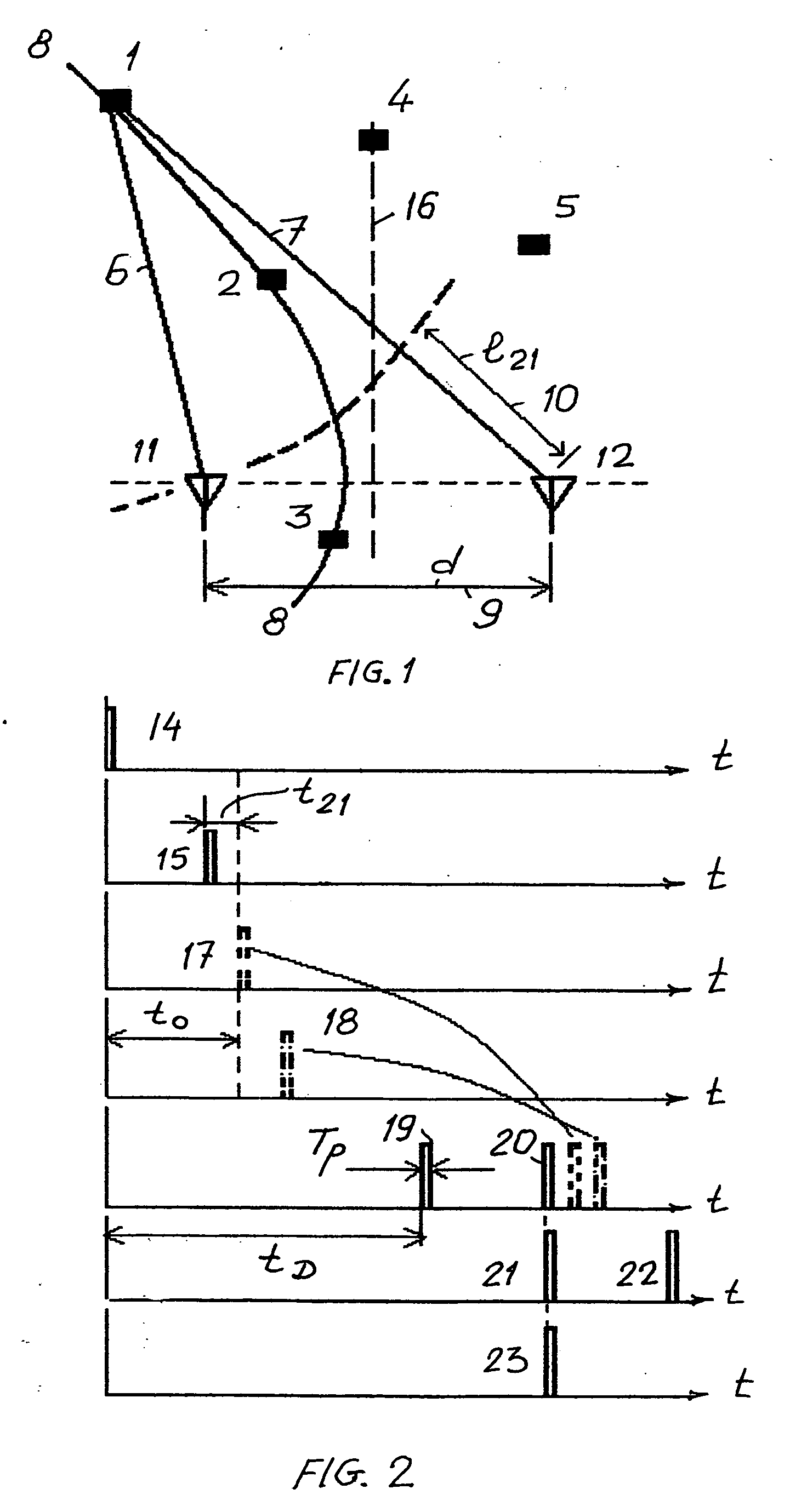
[0057] With reference to the drawings, the procedure of the activation of tags located within an interrogation zone is shown on FIGS. 1 and 2. A tag can be located randomly in points, for example, from Point 1 to Point 5, representing tags 1 to 5 locating at these points on a flat surface in a two-dimensional interrogation zone. If a tag is located at Point 1 and is transmitting a signal, the latter signal 10 reaches the antenna 11 with time delay tD and is received by the antennae 11 and 12 with a time delay having a path length difference l21. This path length difference is constant for any location of tags 1, 2 or 3, for example, on a hyperbolic curve 8.

[0058] Whereas in a reversed situation, namely, signals 14 and 15 are simultaneously transmitted by antennae 11 and 12 respectively, the signal 15 from antenna 12 will reach any tag located on the curve 8 with a delay of 121 / C relative to the signal 14, where C is a signal propagation velocity in the given environment. But if the...


PUM


Abstract

The RFID system is for automatic recognition of each one or all of a plurality of objects located within an interrogation zone. It is applicable for stock-taking or control of goods such as food. The objects provided with tags having transponders carrying RFID codes individually are sequentially scanned and activated one by one. Interrogation signals are transmitted to the tags based on the reader antennas and the configurations and locations of the tags. Signals returned from the transponders of the tags are processed for recognizing the locations of the selected tags and the electronic contents of the tags. The operation continues until the recognition and location of all tags in the entire interrogation zone have been completed.

Description

BACKGROUND OF THE INVENTION [0001] 1. Field of the Invention [0002] This invention relates to systems of maintaining the inventory of objects provided with radio-frequency transducers such as tags or transponders containing electronic codes for their recognition. Such devices are commonly known as radio frequency identification devices (RFID). More specifically, this invention relates to radio-frequency methods of spatial resolution of tags, RFID tag and tag activation device. A RFID consists of a reader and transponders; the latter are affixed on objects which are subject to inventory and are located in a storage such as a warehouse. [0003] 2. Description of Prior Art [0004] RFID methods and systems provide the recognition of objects with identification tags affixed thereon. The process of tag recognition must be accomplished at high speed and with minimum error. In this process it is necessary to determine the tag location or direction relative to a reader. [0005] Each RFID consis...

Claims


Application Information

Patent Timeline
Patent Type & Authority Applications(United States)
IPC IPC(8): H04Q5/22
CPCG01S13/825G01S17/74G06K7/0008G01S15/74
Inventor LEVIN, EDUARD
Owner LEVIN EDUARD
Why Eureka
Try Eureka