Capacitive Keyboard with Non-Locking Reduced Keying Ambiguity

a keyboard and non-locking technology, applied in the direction of coding, pulse technique, keyboard-like device coding, etc., can solve problems such as key ambiguity, and achieve the effect of removing key ambiguity and signal strength valu

Active Publication Date: 2006-08-31
NEODRON LTD
View PDF23 Cites 135 Cited by
  • Summary
  • Abstract
  • Description
  • Claims
  • Application Information

AI Technical Summary

Benefits of technology

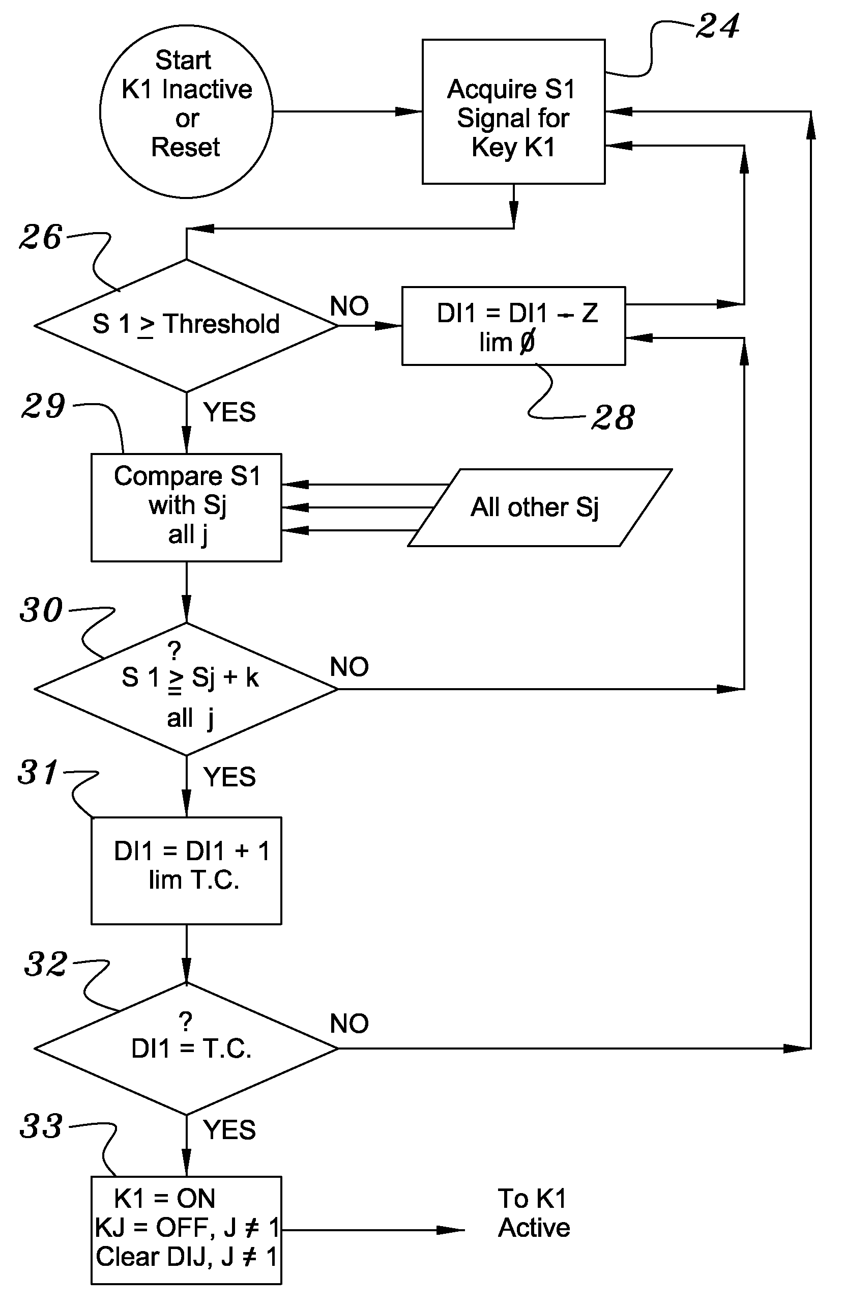
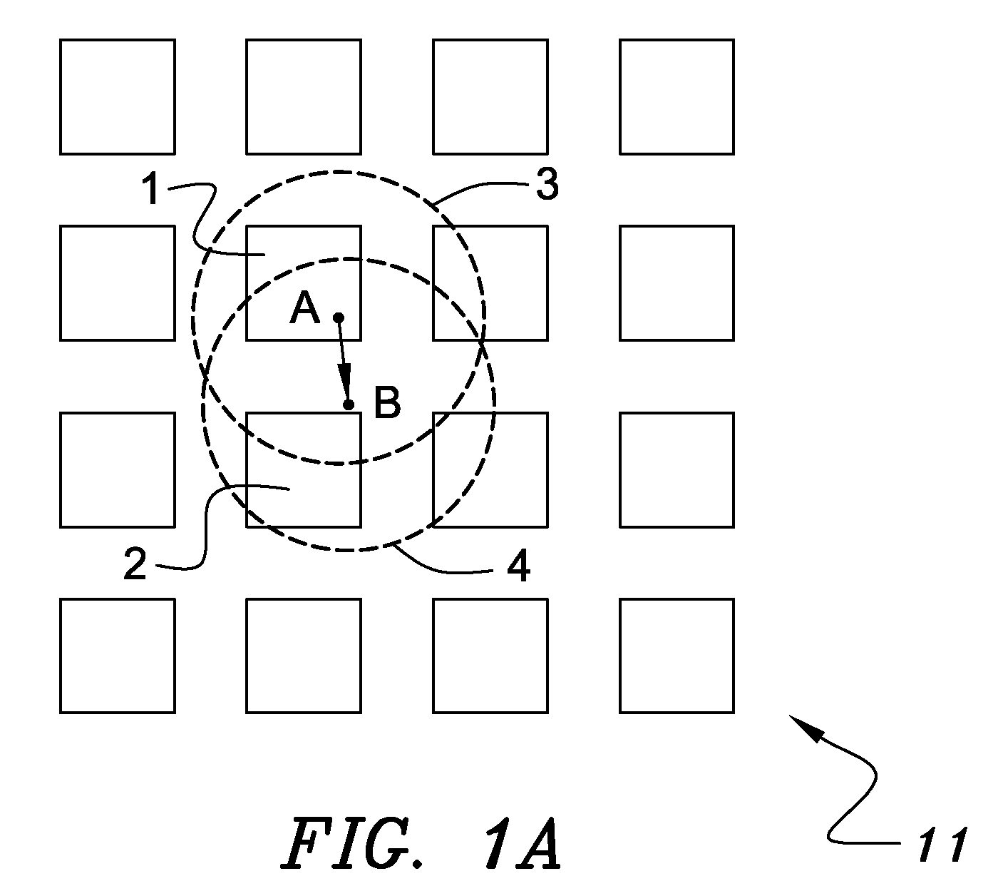
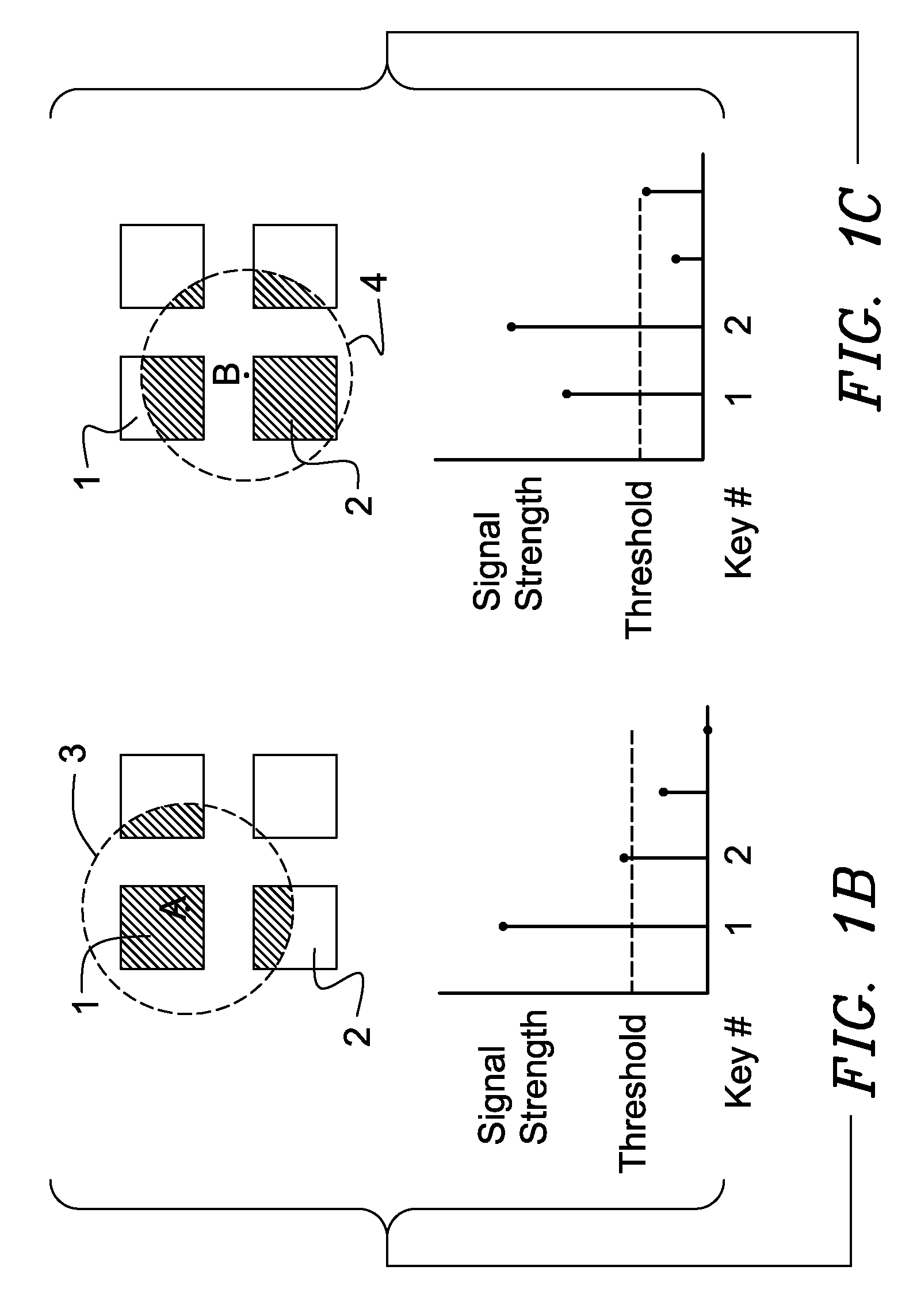
[0007] One aspect of the invention is that it may provide an iterative method of removing keying ambiguity by measuring a detected signal strength associated with each key in an array, comparing the measured signal strengths to find a maximum, determining that the key having the maximum signal strength is the unique user-selected first key, and maintaining that selection until either the first key's signal strength drops below some threshold level or a second key's signal strength exceeds the first key's signal strength. When any key is selected its signal strength value may enhanced relative to all the other keys so as to deselect all other keys. In this aspect, the array under consideration may be a keyboard, or any convenient subset thereof.
[0011] An advantage of this method over those disclosed in my U.S. Pat. No. 6,993,607 is that the method disclosed herein permits the smooth rollover of key selection as a finger slides from one key to the next, while still reducing key ambiguity. In the aforementioned patent, the first key to win remains selected even if the maximal signal strength has shifted to a new key, provided that the first key has enough signal strength left to retain its state, i.e., by having its signal strength in excess of its associated threshold value. Therefore the instant invention may be referred to as ‘non-locking’ key ambiguity reduction.

Problems solved by technology

Conventional capacitive sensors, when tightly packed, or when used in the presence of conductive liquid films, suffer a keying ambiguity problem.
This is especially problematic if the user has large fingers or if he or she presses on the keyboard surface hard enough to deform his or her finger.
Problems of this sort are particularly acute in cash register keyboards used in food service establishments where beverage and food sauce spills are a frequent occurrence.

Method used


Image

  • Capacitive Keyboard with Non-Locking Reduced Keying Ambiguity
  • Capacitive Keyboard with Non-Locking Reduced Keying Ambiguity
  • Capacitive Keyboard with Non-Locking Reduced Keying Ambiguity

Examples


Embodiment Construction

[0022] In studying this Detailed Description, the reader may be aided by noting definitions of certain words and phrases used throughout this patent document. Wherever those definitions are provided, those of ordinary skill in the art should understand that in many, if not most instances, such definitions apply to both preceding and following uses of such defined words and phrases. At the outset of this Description, one may note that the terms “include” and “comprise,” as well as derivatives thereof, mean inclusion without limitation; the term “or,” is inclusive, meaning and / or. The word ‘key’ as generally used in this Disclosure and as specifically used in the Claims attached hereto refers to a touchable portion of a mechanical to electrical transducing device that is non-bistable in nature. This term specifically excludes conventional mechanical switches in which two or more electrical conductors are moved into or away from contact with each other to make or break an electrical co...


PUM


Abstract

Keyboards, keypads and other data entry devices can suffer from a keying ambiguity problem. In a small keyboard, for example, a user's finger is likely to overlap from a desired key to onto adjacent ones. An iterative method of removing keying ambiguity from a keyboard comprising an array of capacitive keys involves measuring a signal strength associated with each key in the array, comparing the measured signal strengths to find a maximum, determining that the key having the maximum signal strength is the unique user-selected key, and maintaining that selection until either the initially selected key's signal strength drops below some threshold level or a second key's signal strength exceeds the first key's signal strength.

Description

[0001] This application is a continuation-in-part of the inventor's U.S. Ser. No. 11 / 160,885, filed on Jul. 14, 2005, which is a continuation of the inventor's U.S. Pat. No. 6,993,607, filed on Jul. 11, 2003, which claimed the priority of his U.S. provisional application 60 / 395,368, filed Jul. 12, 2002. Moreover, this application claims the priority of the inventor's provisional application 60 / 597,851, filed Dec. 21, 2005.BACKGROUND INFORMATION [0002] The invention relates to method and apparatus for controlling an array of non-bistable keys, such as capacitive position sensors, and, more specifically for preventing accidental false inputs from keys adjacent to a selected key in a capacitive keyboard. [0003] Arrays of capacitive proximity sensors are often used in keyboards, keypads and other touch-input apparatus. Two characteristics of capacitive sensors that lead to their use instead of conventional metallic switches are: 1) Capacitive sensors can be made in small sizes, which is...

Claims


Application Information

Patent Timeline
Patent Type & Authority Applications(United States)
IPC IPC(8): H03K17/94H03M11/00
CPCG06F3/0237G06F3/0416H03K2217/960705H03K17/9622H03K17/9643G06F3/044H03K2217/960755G06F3/0202H03M11/02
Inventor PHILIPP, HARALD
Owner NEODRON LTD
Why Eureka
Try Eureka