Apparatus and method for outputting print data

a technology of print data and output method, applied in the field of output method and output output method, can solve the problems of difficult to quickly display an image, difficult to be conspicuous by the angular feeling of the surface,

Inactive Publication Date: 2006-08-31
SEIKO EPSON CORP
View PDF8 Cites 8 Cited by
  • Summary
  • Abstract
  • Description
  • Claims
  • Application Information

AI Technical Summary

Benefits of technology

[0006] It is therefore an object of the present invention to provide a technology allowing an object displayed on a screen to be expressed like an existing object when the object is printed on a medium on which an image can be expressed clearer such as paper.

Problems solved by technology

Naturally, when the size of the polygon is reduced, a number of the polygons serving as the body is increased and therefore, it is difficult to swiftly display an image.
On the other hand, the character is frequently moved during the game to bring about a characteristic that the angular feeling of the surface is difficult to be conspicuous.

Method used


Image

  • Apparatus and method for outputting print data
  • Apparatus and method for outputting print data
  • Apparatus and method for outputting print data

Examples


first embodiment

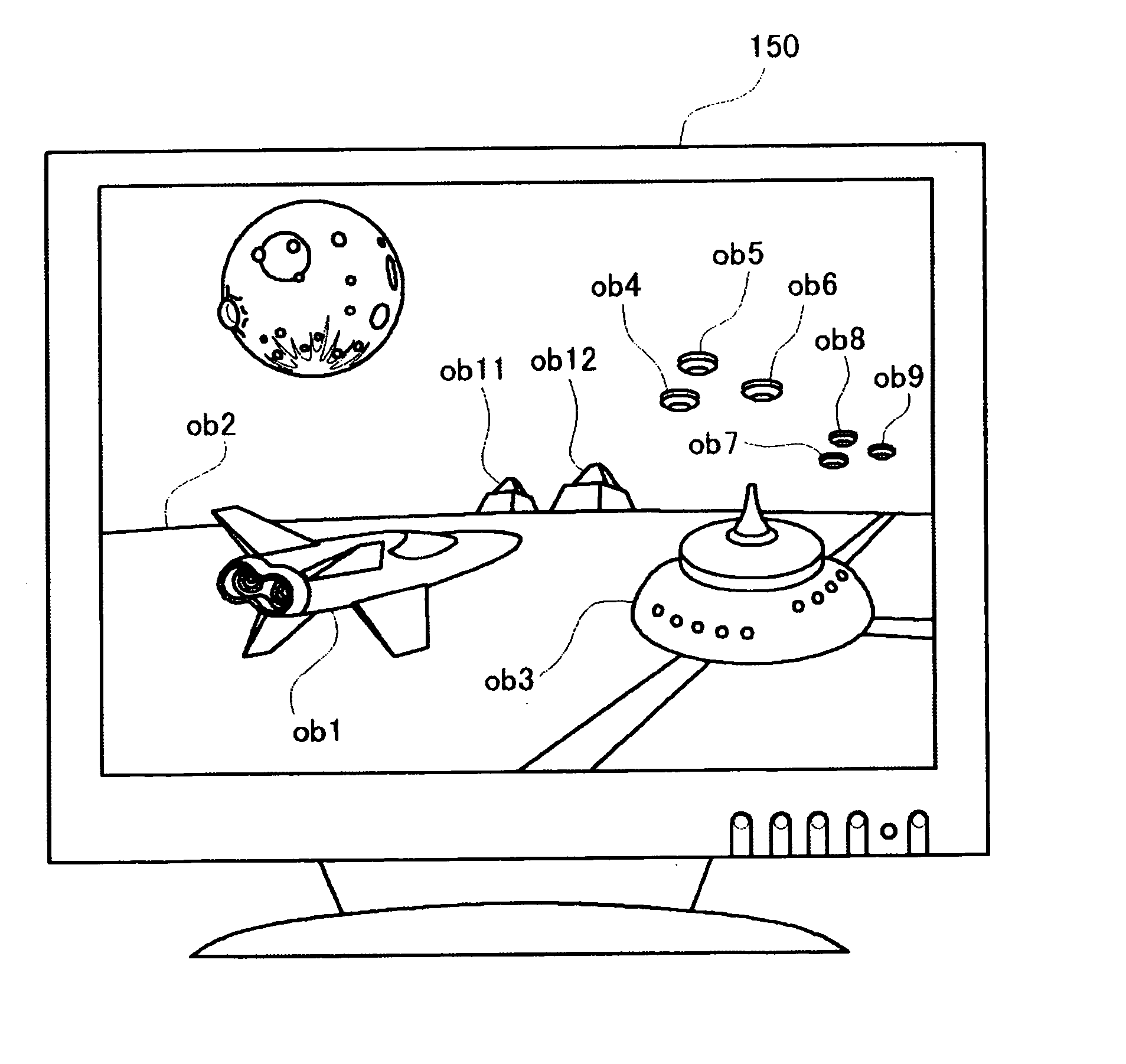
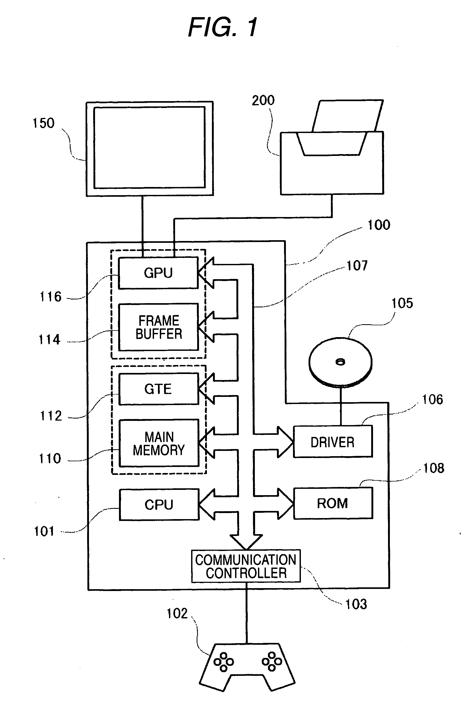
[0069] As shown in FIG. 1, a game machine 100 is constituted by connecting a main memory 110, a coordinates transformer (hereinafter, the GTE: Geometry Transfer Engine) 112, a frame buffer 114, an image processor (hereinafter, the GPU: Graphic Processing Unit) 116, a the ROM 108, a driver 106, a communication controller 103 and the like to be able to exchange data from each other by way of a bus centering on the CPU 101. Further, the game machine 100 is connected with a controller 102 or the like for operating the game machine 100. Further, the game machine 100 is also connected with a color printer 200 to be able to output a screen in the midst of a game by the color printer 200.

[0070] The CPU 101 is a central processing unit for executing so-to-speak arithmetic operation or logical operation, which governs to control a total of the game machine 100. The ROM 108 is a memory exclusive for reading and stored with various programs including a program (boot program) initially executed...

second embodiment

[0194] As shown in FIG. 32, three triangles indicated by solid lines in the figure illustrate the polygons before the division. When the polygons are divided, each polygon is divided into four small polygons by connecting middles points of sides constituting each polygon to each other. In the polygon of a triangle ABC shown in FIG. 32, the triangle ABC can be divided into four small triangles by connecting the middle point ab of side AB, the middle point bc of side BC, and the middle point ac of side AC to each other. Similarly, in the adjacent polygon of triangle BCD, the triangle BCD can be divided into four small triangles by connecting the middle point bc of side BC, the middle point cd of side CD, and the middle point bd of side BD to each other. In this way, the respective polygons constituting an object are divided into four small polygons by repeating such an operation to all the polygons. In step S408 of the image printing processing the processing of dividing the polygons...


PUM


Abstract

In order to output print data representative of an image to be printed by a printer, first image data representative of a first image of an object is generated based on first polygon data representative of a three-dimensional shape of the object with coordinates of apexes of each of first polygons constituting a surface of the object and having a first size. The first image is displayed. When a print instruction for the first image is detected, at least one of the first image data and the first polygon data is acquired to generate second image data representative of a second image of the object which includes second polygon data representative of the three-dimensional shape of the object with coordinates of apexes of each of second polygons constituting the surface of the object and having a second size smaller than the first size. Plural sets of the print data each of which includes a prescribed amount of the second image data are generated. Each of the sets of the print data is sequentially outputted.

Description

BACKGROUND OF THE INVENTION [0001] The present invention relates to a technology of forming to print a two-dimensional image from a three-dimensional data formed by using a computer graphics technology. [0002] In recent years, a virtual world created by imagination can be expressed as if the world were existed by progress of a so-to-speak computer graphics (CG) technology. Further, there has also been developed a game machine in which in a virtual world expressed as if it were existed by utilizing such a technology, a game is advanced by moving a character which is also expressed as if it were existed and the game machine is widely used currently. [0003] In a case of dealing with a three-dimensional body on CG, it is general to use a method of dividing a surface of the body into small plane polygonal shapes and expressing the body by an aggregation of the polygonal shapes. The polygonal shape used for specifying a shape of the body in this way is referred to as “polygon”. Since the ...

Claims


Application Information

Patent Timeline
Patent Type & Authority Applications(United States)
IPC IPC(8): G06T15/00
CPCG06T15/005H04N1/6097
Inventor OTANI, TSUTOMU
Owner SEIKO EPSON CORP
Why Eureka
Try Eureka