
Defect positioning method based on laser ultrasonic B scanning

A laser ultrasonic and defect technology, which is applied in the analysis of solids using sonic/ultrasonic/infrasonic waves, material analysis using sonic/ultrasonic/infrasonic waves, and processing response signals of detection, etc. It can solve the position, shape and size of defects that cannot be intuitively reflected. and other problems, to achieve the effect of highlighting defect signal characteristics, intuitive expression, and improving signal-to-noise ratio

Pending Publication Date: 2020-12-11
XI AN JIAOTONG UNIV
View PDF6 Cites 4 Cited by
  • Summary
  • Abstract
  • Description
  • Claims
  • Application Information

AI Technical Summary

Problems solved by technology

Among them, B-scan can detect more information about defects than A-scan, and has better real-time performance and higher detection efficiency than C-scan, but its result is in the form of stacking of multiple A-scan signals, which cannot be intuitively reflected Defect location, shape and size and other information

Method used


Image

  • Defect positioning method based on laser ultrasonic B scanning
  • Defect positioning method based on laser ultrasonic B scanning
  • Defect positioning method based on laser ultrasonic B scanning

Examples


Embodiment Construction

[0032] The present invention will be described in detail below in conjunction with the accompanying drawings.

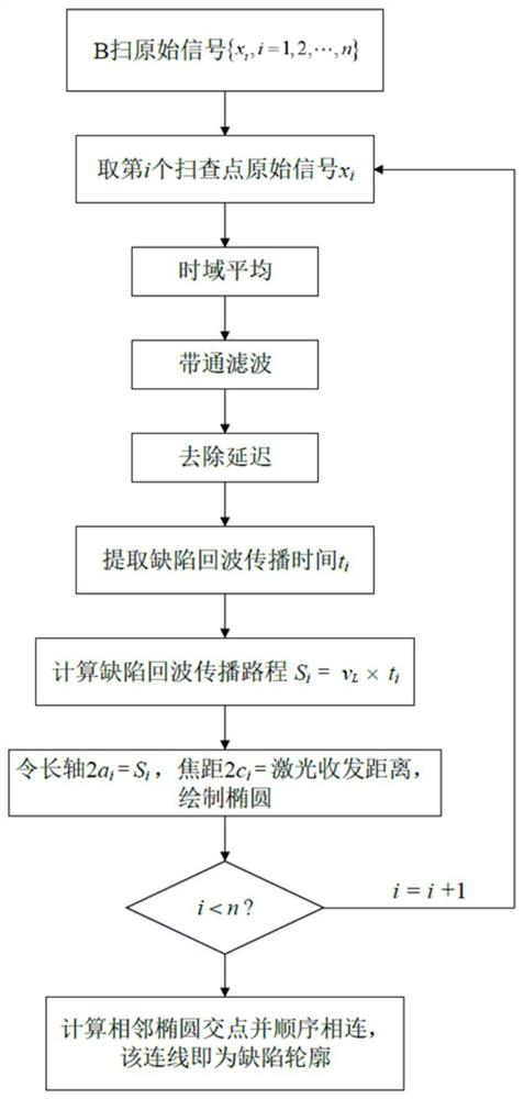
[0033] The defect location method based on the laser ultrasonic B-scan of the present invention reconstructs the B-scan signal into an image, and uses the longitudinal wave to detect the internal defect of the material through the B-scan method. Such as figure 1 As shown, it includes seven parts, which are B-scan, signal processing, extraction of echo peak time, calculation of echo propagation distance, drawing of ellipse, calculation of adjacent ellipse intersection and output image, as follows.

[0034] 1) B-scan

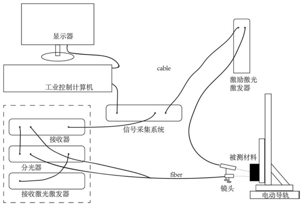
[0035] B-scanning is performed on the upper surface of the aluminum material by moving the excitation laser and the receiving laser at equal intervals at the same time to obtain B-scan signals, and multiple excitations and receptions are performed at each scanning point.

[0036] Specifically, with the help of the existing laser ultrasonic detection pl...


PUM


Abstract

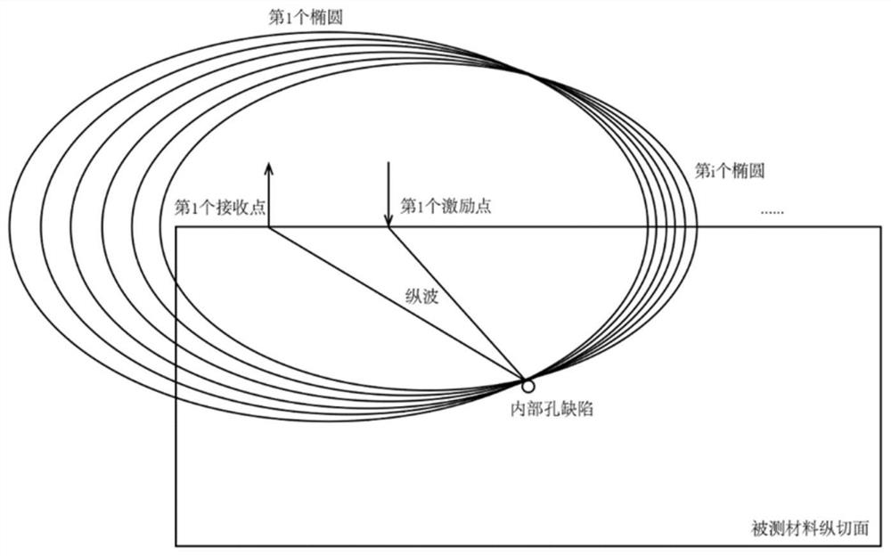
A defect positioning method based on laser ultrasonic B scanning comprises the steps of carrying out B scanning on the surface of a metal material, and acquiring a B scanning signal; preprocessing theB scanning signal, decomposing the B scanning signal into different frequency bands, and extracting a wave crest moment of a longitudinal wave defect echo to obtain a propagation distance of the longitudinal wave of each scanning point; drawing n ellipses by taking an excitation laser point and a receiving laser point as two focuses of the ellipses and taking a longitudinal wave propagation pathas a long axis of the ellipses; and solving the intersection points of the adjacent ellipses, and connecting the intersection points in sequence to obtain the contour of the defect and the position coordinates of the defect. A metal material with internal defects is used as a target verification object, internal defects in a certain longitudinal section are detected through longitudinal waves in aB scanning mode by means of a laser ultrasonic detection platform, reconstruction of B scanning signals is achieved by means of signal noise reduction, feature extraction and the like, and information such as a shape, a size and a position of the defects is detected. And a purpose of visual quantitative identification of defects is achieved.

Description

technical field [0001] The invention relates to the technical field of laser ultrasonic detection, in particular to a method for locating defects based on laser ultrasonic B-scanning. Background technique [0002] Laser ultrasonic technology uses laser pulses to excite ultrasonic waves in the workpiece to be inspected, and uses laser beams to detect the propagation of ultrasonic waves, thereby obtaining workpiece information, such as workpiece thickness, internal and surface defects, material parameters, etc. It combines the high precision of ultrasonic testing and the advantages of non-contact optical testing. Compared with traditional ultrasonic testing, it is more suitable for harsh working environments such as high temperature, high pressure, and strong corrosion, as well as automated testing processes. It has become an important means in the field of nondestructive testing. . [0003] Due to the different propagation characteristics and application occasions of ultraso...

Claims


Application Information

Patent Timeline
Patent Type & Authority Applications(China)
IPC IPC(8): G01N29/06G01N29/44
CPCG01N29/0645G01N29/449G01N2291/0234G01N2291/0289
Inventor 赵纪元赵赢王宇
Owner XI AN JIAOTONG UNIV
Learn More