Image-taking apparatus

a technology of image-taking apparatus and exposure control, which is applied in the direction of optical radiation measurement, exposure control, instruments, etc., can solve the problem of not being able to correct the exposure of the entire screen

Inactive Publication Date: 2006-08-31
FUJIFILM CORP
View PDF2 Cites 32 Cited by
  • Summary
  • Abstract
  • Description
  • Claims
  • Application Information

AI Technical Summary

Benefits of technology

[0035] As described above, according to the invention, it is possible to realize an image-taking apparatus having a light adjustment function to obtain a correct exposure for the entire screen regardless of subject position and distance.

Problems solved by technology

However, a correct exposure for the entire screen cannot be achieved by use of the technique disclosed in this publication alone.

Method used


Image

  • Image-taking apparatus
  • Image-taking apparatus
  • Image-taking apparatus

Examples


first embodiment

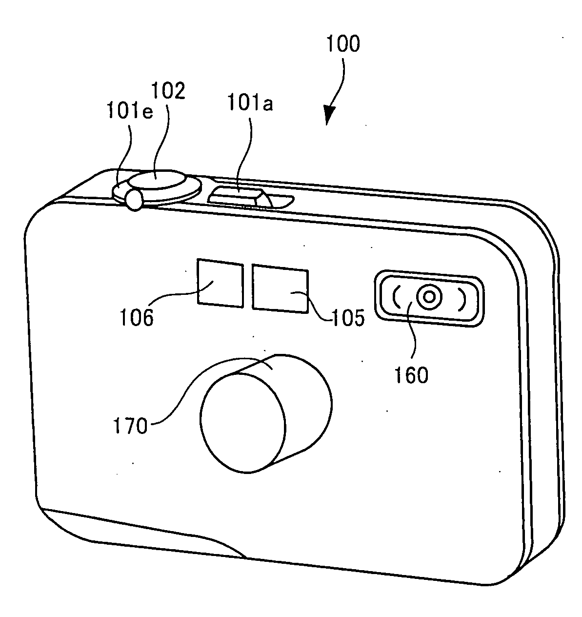
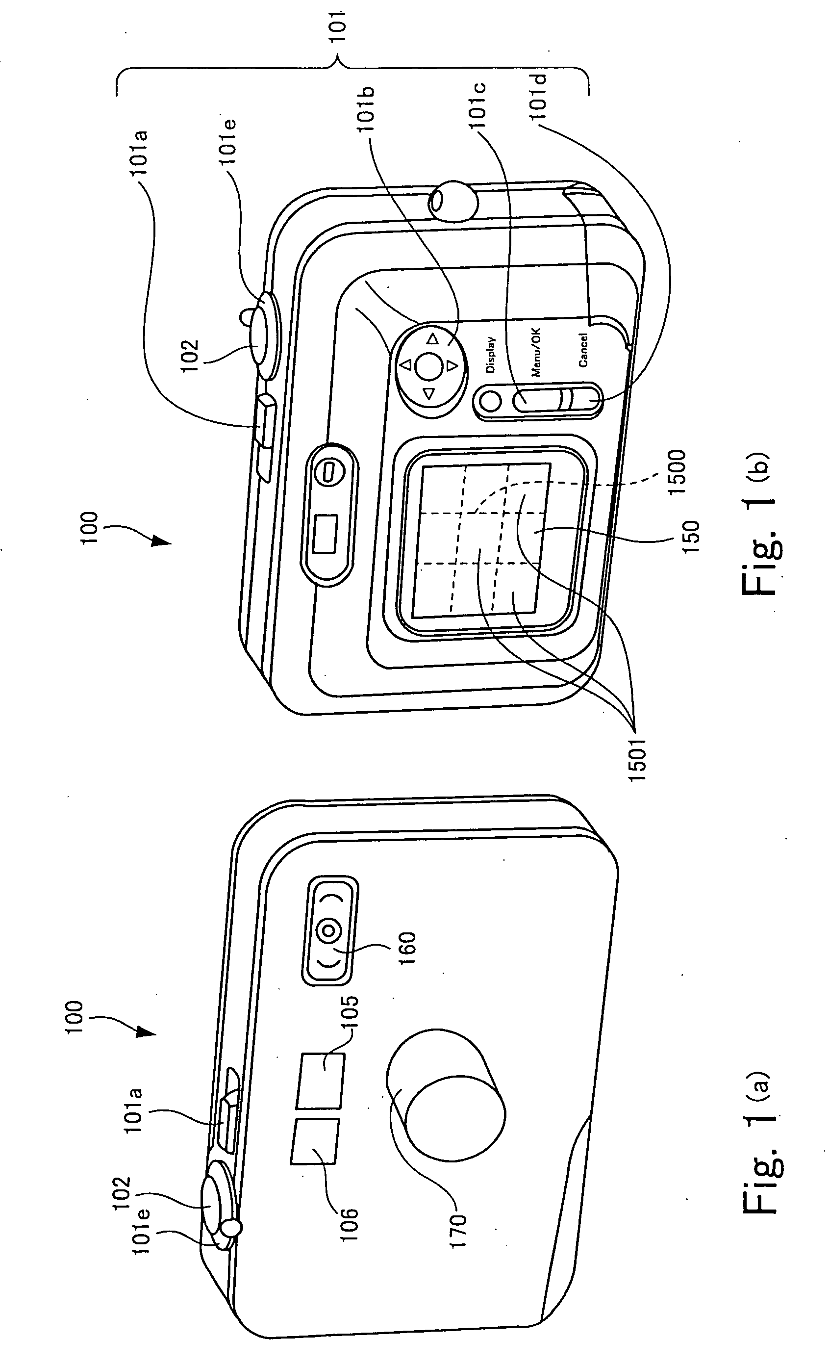
[0053] FIGS. 1(a) and 1(b) show a digital camera according to the image-taking apparatus of the present invention.

[0054] FIGS. 1(a) and 1(b) are perspective views of the front and back of the digital camera according to the first embodiment, as viewed obliquely from above, respectively.

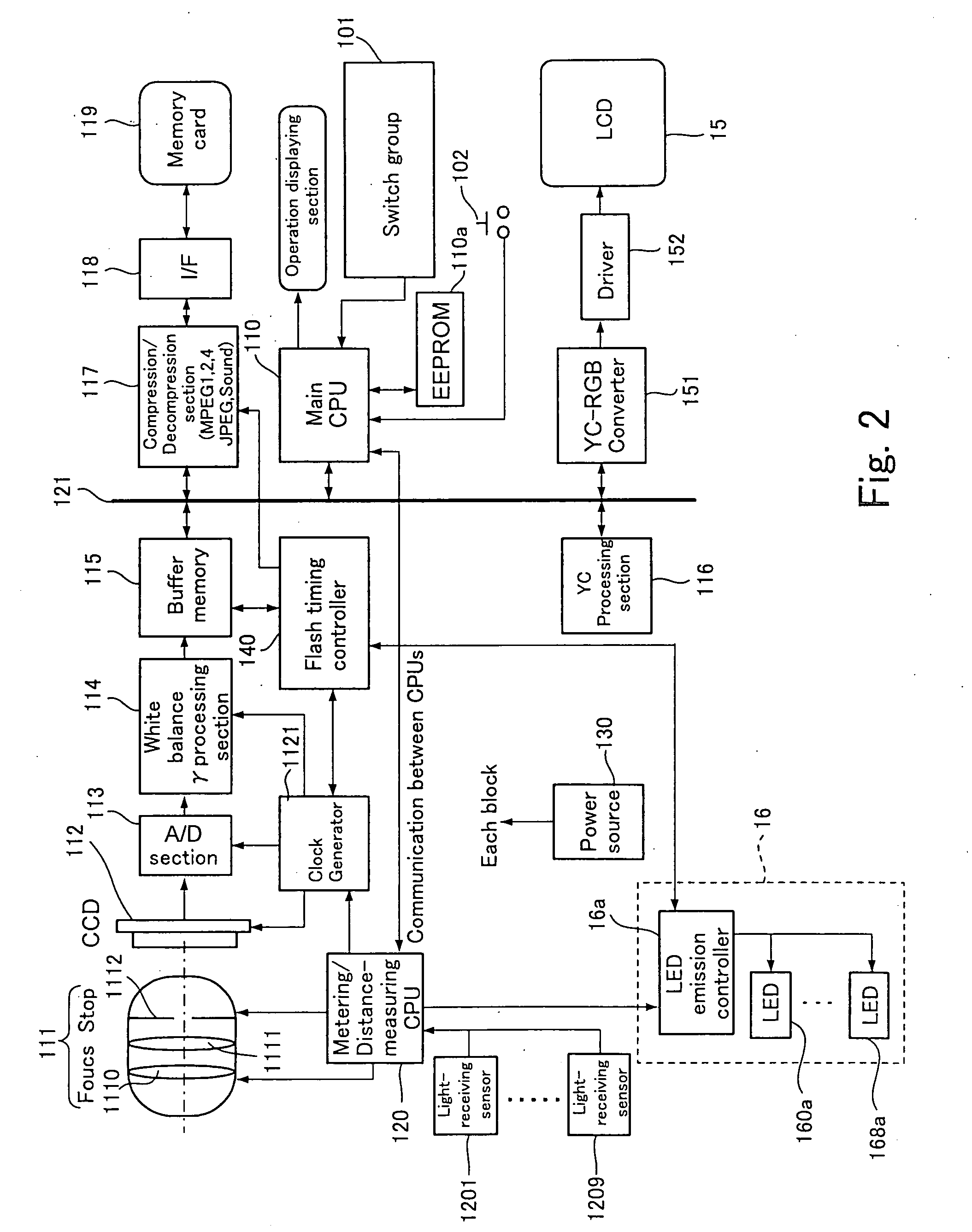
[0055] As shown in FIG. 1(a), a digital camera 100 of the present embodiment has a lens barrel 170 with a built-in shooting lens and a charge-coupled device (CCD) solid imaging device (hereinafter referred to as “CCD”), in which an image of a subject is led to the CCD through the shooting lens. The digital camera 100 is configured such that the CCD generates image signals representing a through image (live view) or a taken image and a main CPU performs through-the-lens (TTL) distance measurement and TTL metering to detect a subject distance and subject brightness. The CCD and the main CPU will be described later more in detail.

[0056] A shooting angle of view is two-dimensionally divided into distanc...

second embodiment

[0093] FIGS. 6(a) and 6(b) show an external appearance of a digital camera 100A according to the FIG. 7 shows an internal configuration of the digital camera 100A shown in FIGS. 6(a) and 6(b). FIGS. 8(a) and 8(b) show a subject area (representing a shooting angle of view) to be captured by an image-taking optical system built in the lens barrel 170 shown in FIGS. 6(a) and 6(b).

[0094] In this digital camera 10A, the main CPU 110 (or metering / distance-measuring CPU 120) performs light adjustment by emitting pre-flash lights and causing the CCD 112 to receive reflected lights from a subject. Therefore, the digital camera 100A is provided with no window similar to the light adjustment window 106 shown in FIG. 1 and no sensors similar to the light-receiving sensors 1201 through 1209 shown in FIG. 2. Except for such difference, the digital camera 100A shown in FIGS. 6(a) and 6(b) is the same as the digital camera 100 shown in FIG. 1.

[0095]FIG. 8(a) shows a shooting angle of view that is...


PUM


Abstract

An image-taking apparatus includes two-dimensionally arranged LEDs for emitting fill lights to eradiation areas. The image-taking apparatus also includes light-receiving sensors for respectively receiving reflected lights from the irradiation areas. The amount of the fill lights or the emission and ceasing of the fill lights are independently controlled so that a correct exposure can be obtained.

Description

BACKGROUND OF THE INVENTION [0001] 1. Field of the Invention [0002] The present invention relates to an image-taking apparatus that includes an imaging device and generates image signals by forming a subject image on the imaging device. [0003] 2. Description of the Related Art [0004] The emergence of blue light-emitting diodes has made it possible to generate white light with light-emitting diodes. As a result, there is a trend to replace incandescent lamps consuming a large amount of power with light-emitting diodes (LED) consuming a small amount of power for the purpose of reducing power consumption. Such a trend has been also seen in the field of digital cameras and the LEDs are replacing xenon tubes used for fill in shooting (see Japanese Patent Application Publication No. 2001-215579 for example). [0005] It is possible to employ multiple light emitters such as LED and allow them to emit fill-flash lights with various light distributions for shooting by changing the light distri...

Claims


Application Information

Patent Timeline
Patent Type & Authority Applications(United States)
IPC IPC(8): G03B15/03G02B7/28G03B15/02G03B7/16G03B7/28G03B15/05H04N5/232H04N5/238H04N101/00
CPCG03B7/16G03B15/05G03B17/02H04N1/40056H04N5/2354H04N2101/00G03B2215/0503G03B2215/0567H04N23/74
Inventor ENDO, HIROSHI
Owner FUJIFILM CORP
Why Eureka
Try Eureka