Bolt-on radial bleed manifold

a radial bleed and bolt-on technology, which is applied in the direction of machines/engines, stators, liquid fuel engines, etc., can solve the problems of thermal response mismatches between the rotor and the case, unfavorable arrangement of the compressor, etc., to achieve positive clearance control, reduce the out-of-roundness of the case, and tighten the clearance

Inactive Publication Date: 2006-08-31
GENERAL ELECTRIC CO
View PDF9 Cites 0 Cited by
  • Summary
  • Abstract
  • Description
  • Claims
  • Application Information

AI Technical Summary

Benefits of technology

[0005] The bolt-on radial bleed manifold configuration eliminates the above-mentioned “diving board” effect, thus providing more positive clearance control between the rotor blade tips and the outer diameter flow path wall. The manifold bleed assembly of this invention also provides new design options for tailoring the case stiffness and the thermal response rate. The stiffness tuning features will permit tighter clearances due to reduced case out-of-roundness, improved gravity sag matching to the rotor and improved thermal response matching to the rotor for hot restarts.

Problems solved by technology

This arrangement is not conducive to reducing compressor clearance, however, because the single shell or case is required to carry the engine loads and to maintain a round, tight clearance flow path.
The current compressor bleed manifold structure further increases the challenge to good case design by disrupting an otherwise smooth load path; creating unsupported case wall sections which lead to the so-called “diving board” effect; limiting extraction pipe locations and resultant loads into the case; and creating thermal response mismatches between the rotor and the case.

Method used


Image

  • Bolt-on radial bleed manifold
  • Bolt-on radial bleed manifold
  • Bolt-on radial bleed manifold

Examples


Embodiment Construction

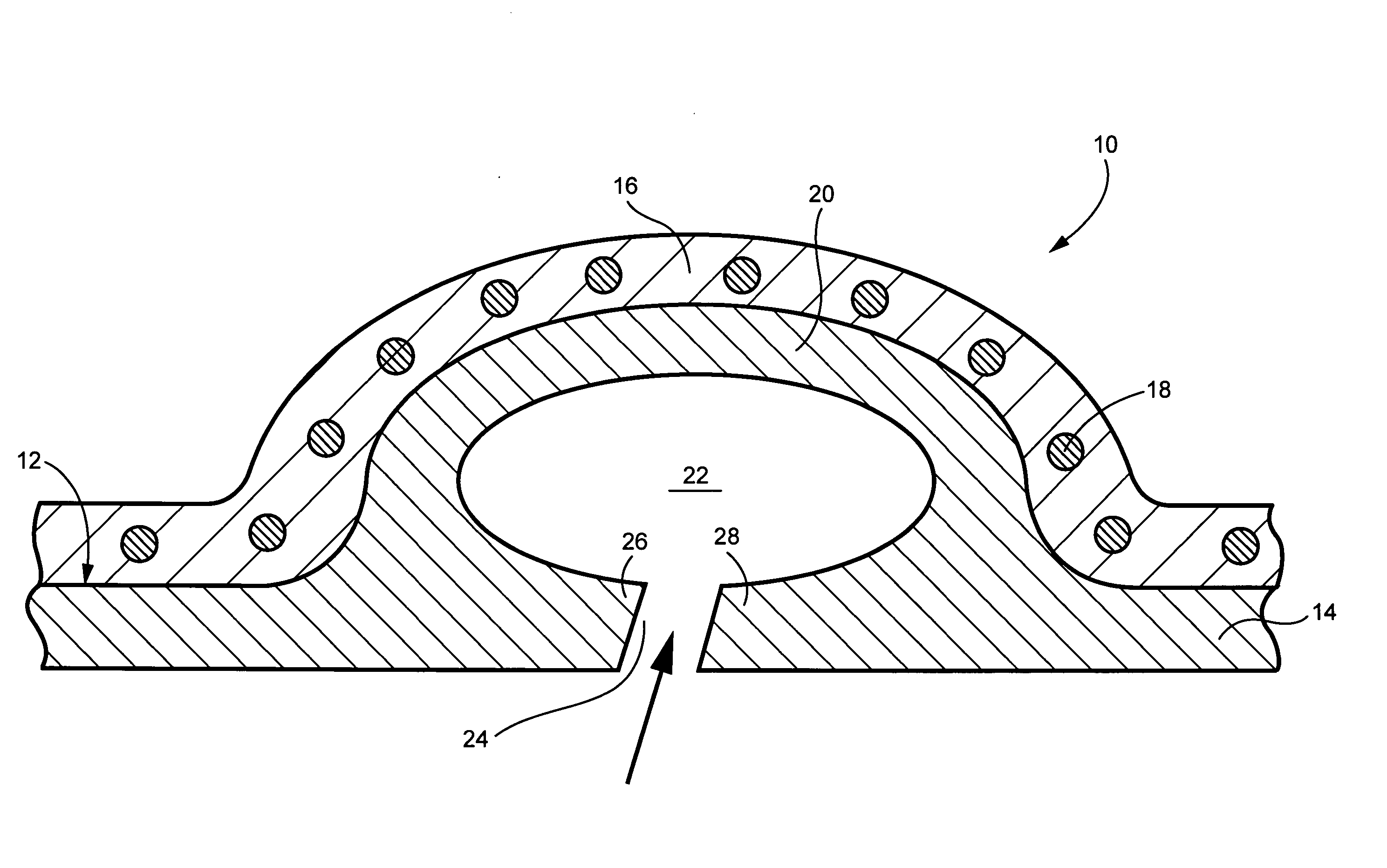
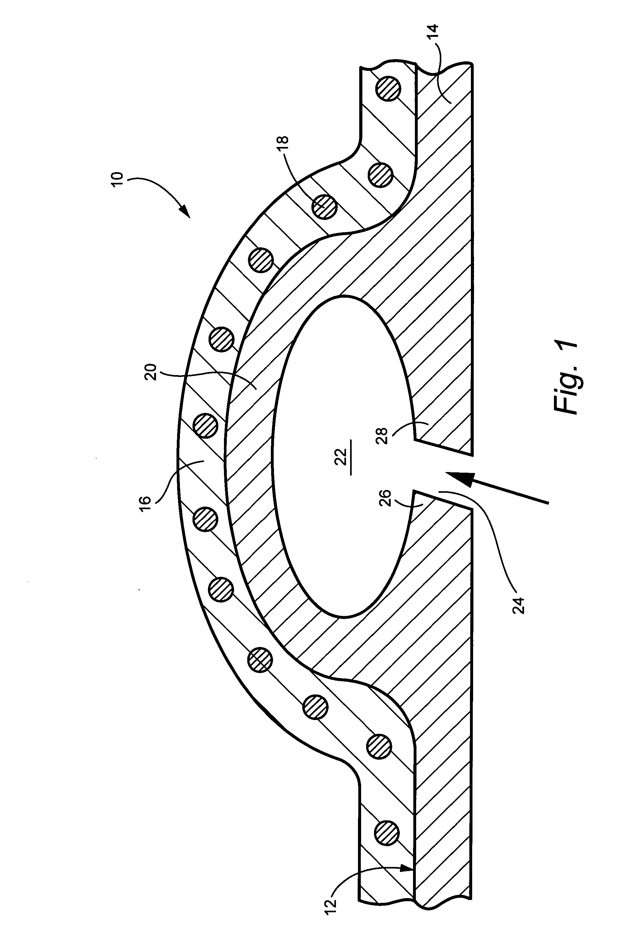
[0014]FIG. 1 illustrates a conventional bleed slot and manifold configuration 10 for a compressor 12. The compressor case 14 is formed by two half sections, joined along a split vertical flange 16 by bolts 18 or the like. The manifold 20 is integral with the case wall and includes a plenum 22 and a continuous, annular inlet slot 24 connecting the plenum 22 with the interior flow path of the compressor 12. Note the unsupported marginal portions 26, 28 of the case 14 on either side of the slot 24. These unsupported case portions may deflect inwardly and / or outwardly, leading to what is commonly referred to as a “diving board” effect that negatively impacts on the ability to control tight flow path clearances between the compressor blades (not shown) and the case wall. Also note that the bolt hole pattern for bolts 18 adjacent the plenum 22 are spaced radially outwardly of the plenum and the inlet slot 24 which negatively impacts the stiffness of the case, particularly in the area of m...


PUM


Abstract

A compressor radial bleed manifold and compressor case assembly includes a compressor case having one or more bleed flow exit passages therein; and a discrete bleed manifold mounted on the compressor case and having one or more inlet passages extending radially between a manifold plenum and the one or more exit passages in the mounting boss for bleeding compressor air into the manifold plenum.

Description

BACKGROUND OF THE INVENTION [0001] This invention relates to rotary machine technology and specifically, to a discrete compressor bleed manifold attachable to the associated compressor case. [0002] Reducing radial clearance between rotating compressor blades and the compressor case in axial flow industrial gas turbines is essential for improved performance. Current industrial gas turbine compressor bleed manifolds are integral to the basic compressor case structure. In other words, the current industrial turbine case design philosophy integrates the bleed manifold with the compressor case. This arrangement is not conducive to reducing compressor clearance, however, because the single shell or case is required to carry the engine loads and to maintain a round, tight clearance flow path. Such manifolds typically include opposed manifold sections joined along axially extending, opposed vertical flanges by a plurality of transversely oriented bolts. These bolts are necessarily far remov...

Claims


Application Information

Patent Timeline
Patent Type & Authority Applications(United States)
IPC IPC(8): F01B25/00
CPCF01D9/026F01D17/105F02C6/08F04D29/545
Inventor MARTIN, NICHOLAS FRANCISCENCULA, JAMES EDWARD
Owner GENERAL ELECTRIC CO
Why Eureka
Try Eureka