Systems and methods for assembling a front end module to a vehicle

a front end module and assembly system technology, applied in the field of vehicle assembly, can solve the problems of time-consuming and complex assembly of existing fem assemblies, damage to vehicle fenders, and plant operators' specific skill and care, and achieve the effects of tighter clearance, reduced assembly cost, and reduced assembly cos

Inactive Publication Date: 2011-08-02
FCA US
View PDF11 Cites 3 Cited by
  • Summary
  • Abstract
  • Description
  • Claims
  • Application Information

AI Technical Summary

Benefits of technology

[0003]In various exemplary embodiments, the present disclosure provides a FEM assembly and associated assembly method with a rail system to guide the front end module assembly onto a frame of the vehicle enabling efficient assembly, tighter clearances between the FEM assembly and the vehicle, and protection of the FEM assembly and the vehicle from damage during assembly. The present disclosure provides a FEM assembly including grilles and headlamps and a rail system enabling the FEM assembly to be assembled on a vehicle. Advantageously, the present disclosure allows the FEM assembly to pass between fenders on the vehicle with a very tight clearance condition. The rail system included in the present disclosure allows the FEM assembly to be assembled efficiently while protecting grilles and headlamps from being damaged by fenders and protecting the fenders from damage from the FEM assembly. The rail system substantially constrains movement of the FEM assembly when being placed onto the vehicle during assembly avoiding contact with any portion of the fenders in a dynamic condition. The rail system includes a guide on the fenders, such as a fender reinforcement bracket tab, and a rail connected to the FEM assembly. Once the FEM is in the final installation position, the rail can be disengaged from the fender, allowing final assembly by rotating the FEM rearward.
[0004]In an exemplary embodiment of the present disclosure, a front end module assembly for a vehicle includes a front end module carrier and a rail disposed on the front end module carrier, wherein the rail is configured to engage a tab disposed on a fender of the vehicle, and the rail is configured to substantially constrain movement of the front end module assembly while the front end module assembly is positioned on a frame on the vehicle. The front end module assembly further includes any of a grille, a headlamp housing, a coolant module, and combinations thereof. The fender includes a fender reinforcement bracket, and the tab is disposed on the fender reinforcement bracket. The substantially constrained movement of the front end assembly while the front end module assembly is positioned allows the front end module assembly to pass between fenders on the vehicle with a tight clearance condition. The carrier rail and the tab are configured to guide the front end module assembly onto the vehicle for assembly avoiding front end module assembly contact with any portion of the fender. The substantially constrained movement of the front end assembly while the front end module assembly is positioned protects the grille and headlamp housing from being damaged by the fender, and protects the fender from being damaged by the front end module assembly. The carrier rail is one of integrally formed with the front end module carrier and mountably attached to the front end module carrier.
[0005]In another exemplary embodiment of the present invention, a method of assembling a front end module assembly onto a vehicle frame includes providing a front end module assembly, wherein the front end module assembly includes a rail disposed on a front end module carrier; positioning the front end module assembly substantially over a vehicle frame; engaging the rail with a tab disposed on the vehicle frame; and guiding the front end module assembly into a final assembly position on the vehicle frame, wherein the rail and the tab are configured to substantially constrain movement of the front end module assembly during the guiding step. The method of assembling a front end module assembly of further includes disengaging the rail from the tab and attaching the front end module assembly to the vehicle frame. The front end module assembly further includes any of a grille, a headlamp housing, a coolant module, and combinations thereof. The vehicle frame includes a fender, and the fender includes a fender reinforcement bracket, and wherein the tab is disposed on the fender reinforcement bracket. The substantially constrained movement of the front end assembly of the guiding step allows the front end module assembly to pass between fenders on the vehicle with a tight clearance condition. The rail and the tab are configured to guide the front end module assembly onto the vehicle frame avoiding front end module assembly contact with any portion of a fender attached to the vehicle frame. The substantially constrained movement of the front end assembly of the guiding step protects the grille and headlamp housing from being damaged by a fender attached to the vehicle frame and protects the fender from being damaged by the front end module assembly. The rail is integrally formed with the front end module carrier and mountably attached to the front end module carrier.

Problems solved by technology

Despite the advantages of the modular FEM assembly, assembling existing FEM assemblies is time-consuming and complex.
Existing FEM assemblies and assembly methods include complicated lift and positioning plant assist devices.
Further, plant operators require specific skill and care to assemble such existing FEM assemblies.
Finally, existing FEM assemblies are prone to damaging vehicle fenders and FEM grilles costing considerable repair time and cost during assembly followed by increased warranty costs on possible corrosion in the fenders due to damage from assembly.
Accordingly, current FEM assemblies do not allow tight gaps to exist between the FEM and fenders with frontal projections without damaging both parts during regular production processes.

Method used


Image

  • Systems and methods for assembling a front end module to a vehicle
  • Systems and methods for assembling a front end module to a vehicle
  • Systems and methods for assembling a front end module to a vehicle

Examples


Embodiment Construction

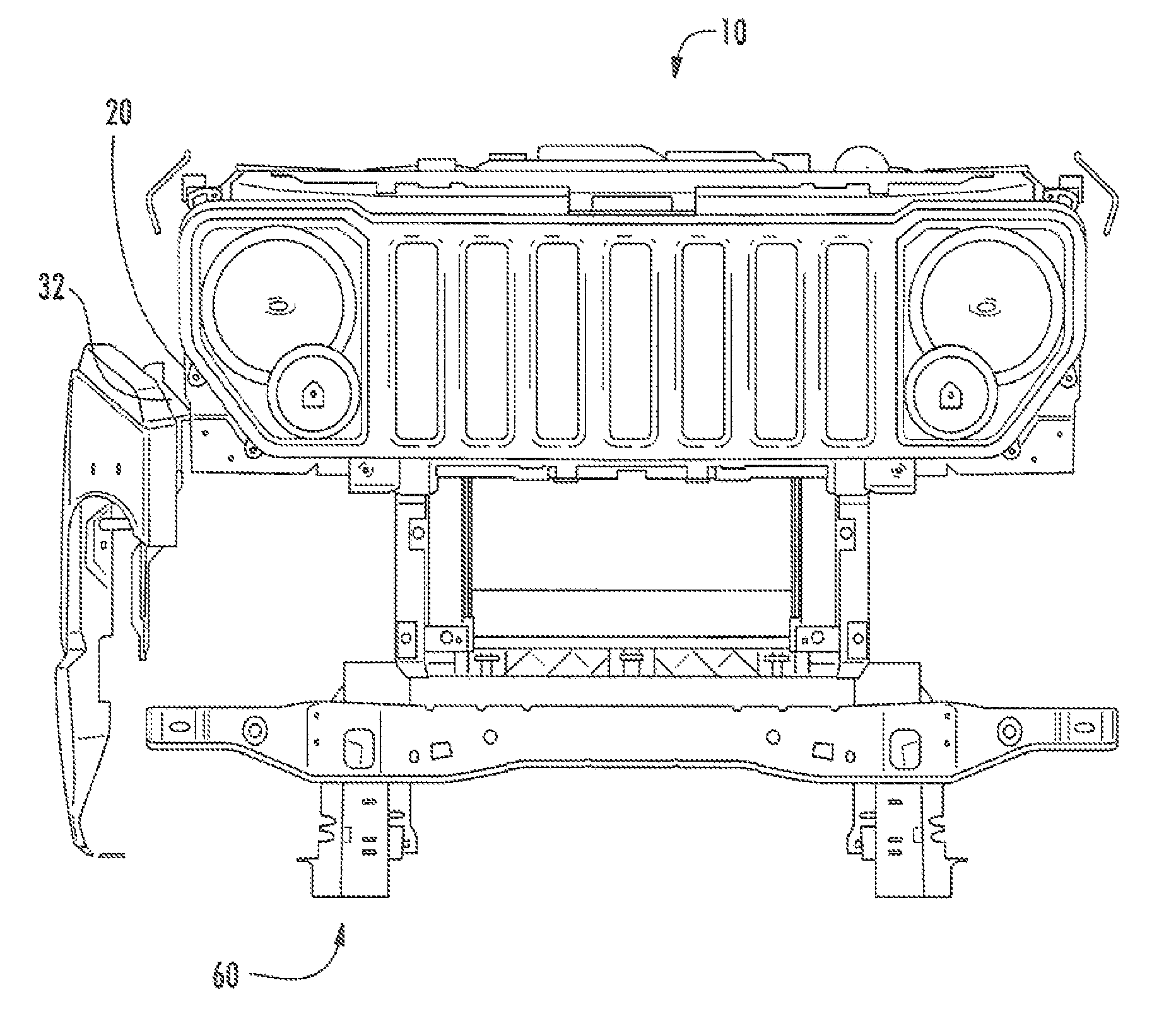
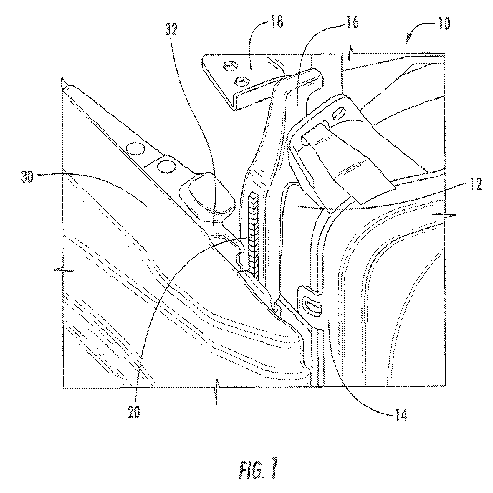
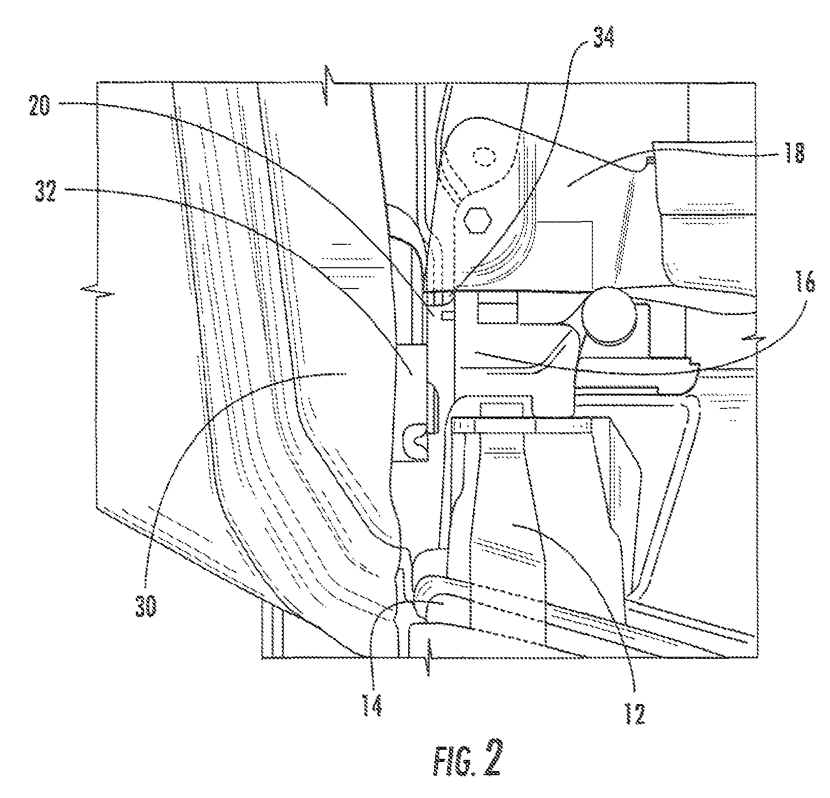
[0025]In various exemplary embodiments, the present disclosure provides a FEM assembly and associated assembly method with a rail system to guide the front end module assembly onto a frame of a vehicle enabling efficient assembly, tighter clearances between the FEM assembly and the vehicle, and protection of the FEM assembly and the vehicle from damage during assembly. The present disclosure provides a FEM assembly including grilles and headlamps and a rail system enabling the FEM assembly to be assembled on a vehicle. Advantageously, the present disclosure allows the FEM assembly to pass between fenders on the vehicle with a very tight clearance condition. The rail system including in the present disclosure allows the FEM assembly to be assembled efficiently while protecting grilles and headlamps from being damaged by fenders, and protecting the fenders from damage from the FEM assembly. The rail system substantially constrains movement of the FEM assembly when being placed onto th...


PUM

PropertyMeasurementUnit
corrosionaaaaaaaaaa
movementaaaaaaaaaa

Abstract

The present disclosure provides a Front End Module (FEM) assembly and associated assembly method with a rail system to enable efficient assembly, tighter clearances between the front end module assembly and the vehicle, and time and cost savings. The present disclosure provides a FEM assembly including grilles and headlamps and a rail system enabling the FEM to be assembled on a vehicle. Advantageously, the present disclosure allows the FEM to pass between fenders on the vehicle with a very tight clearance condition. The rail system included in the present disclosure allows the FEM to be assembled efficiently while protecting grilles and headlamps from being damaged by fenders and protecting the fenders from damage from the FEM.

Description

FIELD OF THE DISCLOSURE[0001]The present disclosure relates generally to vehicle assembly. More specifically, the present disclosure relates to a front end module assembly and an associated assembly method which includes a rail system to guide the front end module assembly onto a frame of the vehicle enabling efficient assembly, tighter clearances between the front end module assembly and the vehicle, and protection of the front end module assembly and the vehicle front damage during assembly.BACKGROUND OF THE DISCLOSURE[0002]Vehicles include a front end module (FEM) assembly with a front fascia to provide openings for cooling air. Additionally, the FEM can include a vehicle-specific grille texture, headlamp housing, means to connect to the vehicle frame and bumper, and the like. Advantageously, FEM assemblies benefit vehicle assemblers through a modular assembly approach allowing component integration, time and cost savings, and the like. Despite the advantages of the modular FEM a...

Claims


Application Information

Patent Timeline
Patent Type & Authority Patents(United States)
IPC IPC(8): B60K11/04
CPCB62D25/084B62D65/04Y10T29/49895
Inventor GONZALEZ-SALVADOR, BERNARDO
Owner FCA US
Why Eureka
Try Eureka