Implant system and fastening element for an implant system

a technology of fastening element and implant system, which is applied in the field of fastening element for implant system, can solve the problems of limited pivot angle on all sides and extreme care in the way, and achieve the effects of improving clamping, simple manufacturing, and good support of connecting element on the receiving par

Inactive Publication Date: 2006-08-31
AESCULAP AG
View PDF28 Cites 101 Cited by
  • Summary
  • Abstract
  • Description
  • Claims
  • Application Information

AI Technical Summary

Benefits of technology

[0035] According to a further preferred form of construction of the invention, it may be provided that the clamping element has a proximal end that has relative to the reference plane an inclined connecting-element seating surface facing in proximal direction, that the connecting-element receiver comprises at least one connecting-element-receiver seating surface facing in proximal direction and that the connecting element in the fixing position lies partially against the connecting-element seating surface and partially against the at least one connecting-element-receiver seating surface and is inclined by the connecting-element angle of inclination relative to the reference plane. In other words, in this development the connecting element lies partially against the connecting-element receiver and partially against the proximal end of the clamping element. In this way, an asymmetrical introduction of force from the fixing element via the connecting element to the connecting-element receiver and the clamping element is realized. As a result of this, forces may be introduced not only parallel to, but also transversely of, the longitudinal axis or axis of symmetry of the fixing element. This additionally allows a marked improvement of a clamping between the clamping element and the proximal end of the fastening part.
[0036] To allow the connecting element to lie with the greatest possible surface area in contact with the clamping element, it is advantageous when the angle of inclination corresponds or substantially corresponds to the clamping-element angle of inclination. In combination with an outer surface of the fixing element that is inclined at the same angle, a particularly good support of the connecting element on the receiving part may be achieved.
[0037] The clamping element is particularly simple to manufacture when it is of a sleeve-shaped design. It moreover affords free access through a likewise sleeve-like receiving part to the proximal end of the fastening part in order, for example, to fix the fastening element in a bone part.
[0038] In principle, the fastening part might be of any shape that allows the fastening part to be fixed in or on a bone or the like. Preferably, the fastening part is designed in the form of a bone screw or a bone hook. The fastening part may then easily be driven or hooked and / or screwed into a bone.
[0039] An implant system of the initially described type can be improved according to the invention in that at least one of the at least two fastening elements is one of the previously described fastening elements. By means of the previously described fastening elements a connecting element is fastenable in a desired manner in the region of the cervical vertebrae. In particular, it is thereby possible to achieve a, compared to conventional implant systems, particularly acute angle between a longitudinal direction defined by the fastening part and a longitudinal direction defined by the connecting element.
[0040] A particularly simple construction of the implant system arises when the connecting element is a rod or a plate having a rod-shaped portion.

Problems solved by technology

The use of such bone screws is problematical in the region of the cervical vertebrae since, because of the design of the articulated connection between the fastening portion and the receiving part of the bone screw, a pivoting angle is limited on all sides.
The drawback of this development is that, when the implant system is inserted, extreme care has to be taken regarding the way in which the fastening parts of the bone screws are screwed into the vertebral bodies.

Method used


Image

  • Implant system and fastening element for an implant system
  • Implant system and fastening element for an implant system
  • Implant system and fastening element for an implant system

Examples


Embodiment Construction

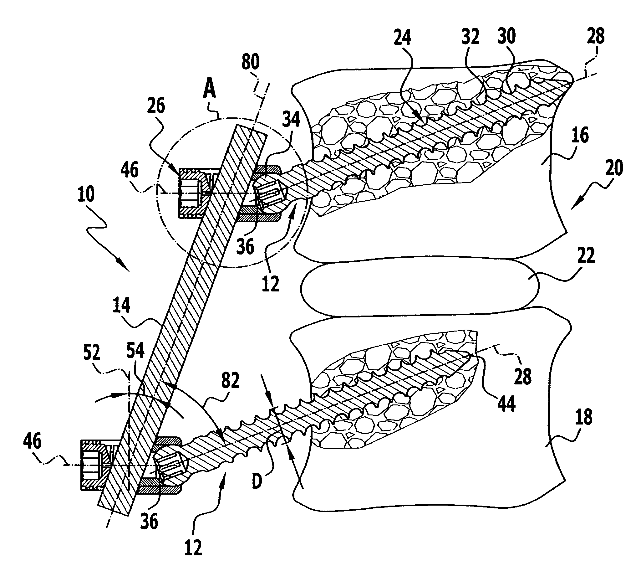
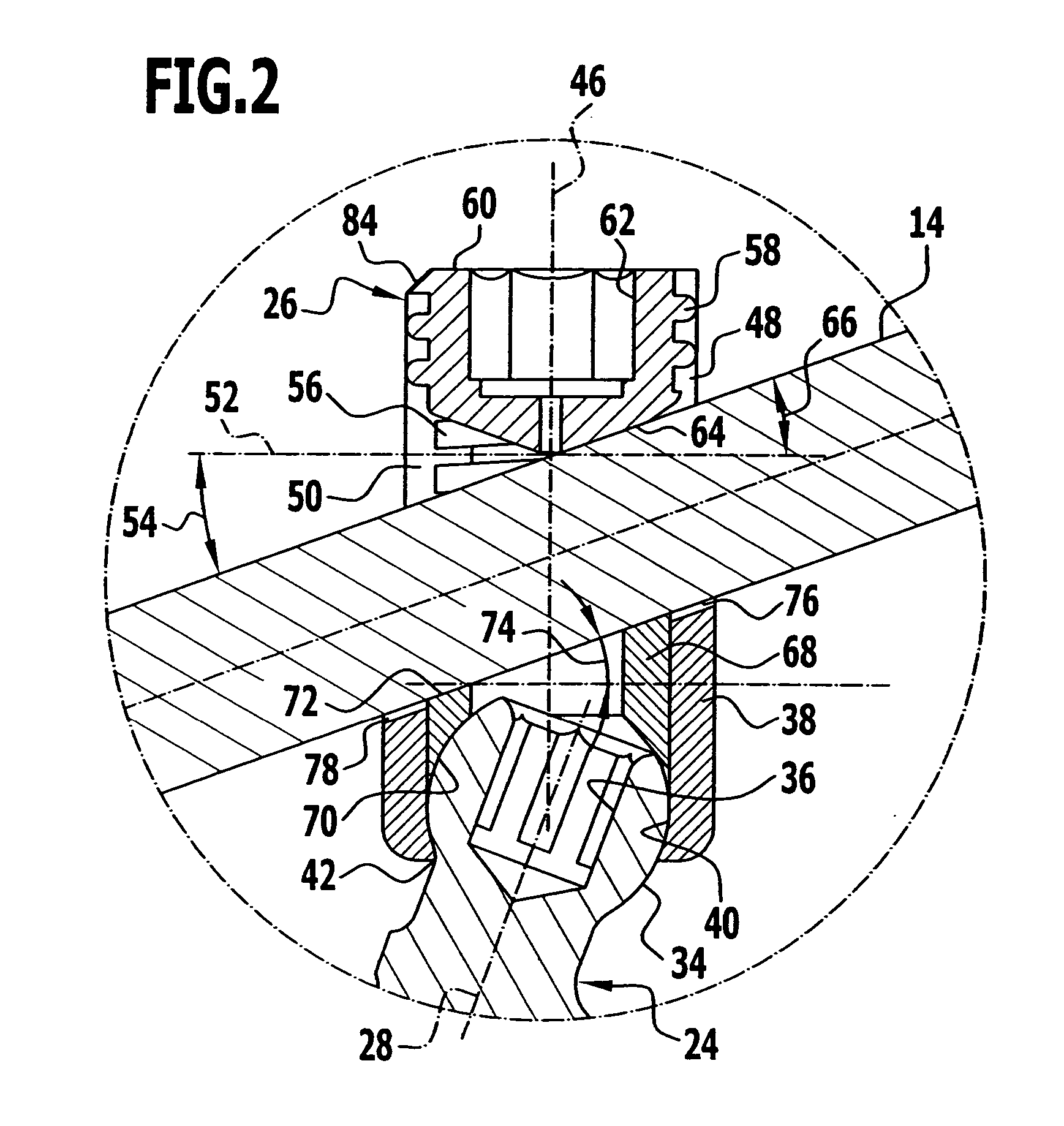
[0046] In FIG. 1 an implant system according to the invention provided as a whole with the reference character 10 is illustrated by way of example. In the illustrated embodiment, the implant system comprises two identical fastening elements in the form of polyaxial bone screws 12 as well as a connecting element in the form of a rod 14. By means of the implant system 10 two adjacent vertebrae 16 and 18 of a human or animal vertebral column 20 may be fixed relative to one another. Particularly in the case of damaged cervical vertebrae 16 and / or 18 or a damaged intervertebral disk 22 between them, the implant system 10 may be inserted dorsally for stabilization. The implant system 10 therefore forms a stabilizing system for the vertebral column.

[0047] There now follows a detailed description of the construction of the implant system 10.

[0048] The rod 14 is elongate and has a circular cross section. It would also be conceivable to use an inwardly curved, non-rectilinearly extending ro...


PUM


Abstract

The present invention relates to a fastening element for an implant system, which comprises at least two fastening elements fixable to bone parts or the like and at least one connecting element fixable to the at least two fastening elements, wherein the fastening element comprises a fastening part with a fastening portion at the distal end as well as a receiving part connected to the fastening part, wherein the receiving part comprises a connecting-element receiver for receiving the connecting element as well as a fixing element for fixing the fastening element in the connecting-element receiver, wherein the connecting-element receiver is designed asymmetrically in relation to an axis of symmetry or longitudinal axis of the fixing element.

Description

[0001] The present disclosure relates to the subject matter disclosed in German patent application 10 2005 009 282.9 of Feb. 22, 2005, which is incorporated herein by reference in its entirety and for all purposes. BACKGROUND OF THE INVENTION [0002] The present invention relates to a fastening element for an implant system, which comprises at least two fastening elements fixable to bone parts or the like and at least one connecting element fixable to the at least two fastening elements, wherein the fastening element comprises a fastening part with a fastening portion at the distal end as well as a receiving part connected to the fastening part, wherein the receiving part comprises a connecting-element receiver for receiving the connecting element as well as a fixing element for fixing the fastening element in the connecting-element receiver. [0003] The present invention further relates to an implant system having at least two fastening elements fixable to bone parts or the like as w...

Claims


Application Information

Patent Timeline
Patent Type & Authority Applications(United States)
IPC IPC(8): A61F2/30
CPCA61B17/7032A61B17/7037
Inventor SCHUMACHER, JORG
Owner AESCULAP AG
Why Eureka
Try Eureka