Spinal fusion system utilizing an implant plate having at least one integral lock

Active Publication Date: 2006-08-31
X SPINE SYST
View PDF99 Cites 54 Cited by
  • Summary
  • Abstract
  • Description
  • Claims
  • Application Information

AI Technical Summary

Benefits of technology

[0012] Another object of one embodiment is to provide a plurality of screws that are cap

Problems solved by technology

Among some of the problems associated with the prior art devices is that after the device is inserted into a patient during a surgical procedure, there was a possibility of retropulsion of the inter-body device and graft material into the spinal cord or other neurological element.
Another problem with the prior art devices is that grafting material, which was inserted into the devices during the surgical procedure, could not easily be inserted from an anterior direction.
Moreover, in some of the prior art devices, the cover, if any, was typically fastened directly to the device and to spinal bones, which prevented

Method used


Image

  • Spinal fusion system utilizing an implant plate having at least one integral lock
  • Spinal fusion system utilizing an implant plate having at least one integral lock
  • Spinal fusion system utilizing an implant plate having at least one integral lock

Examples


Example

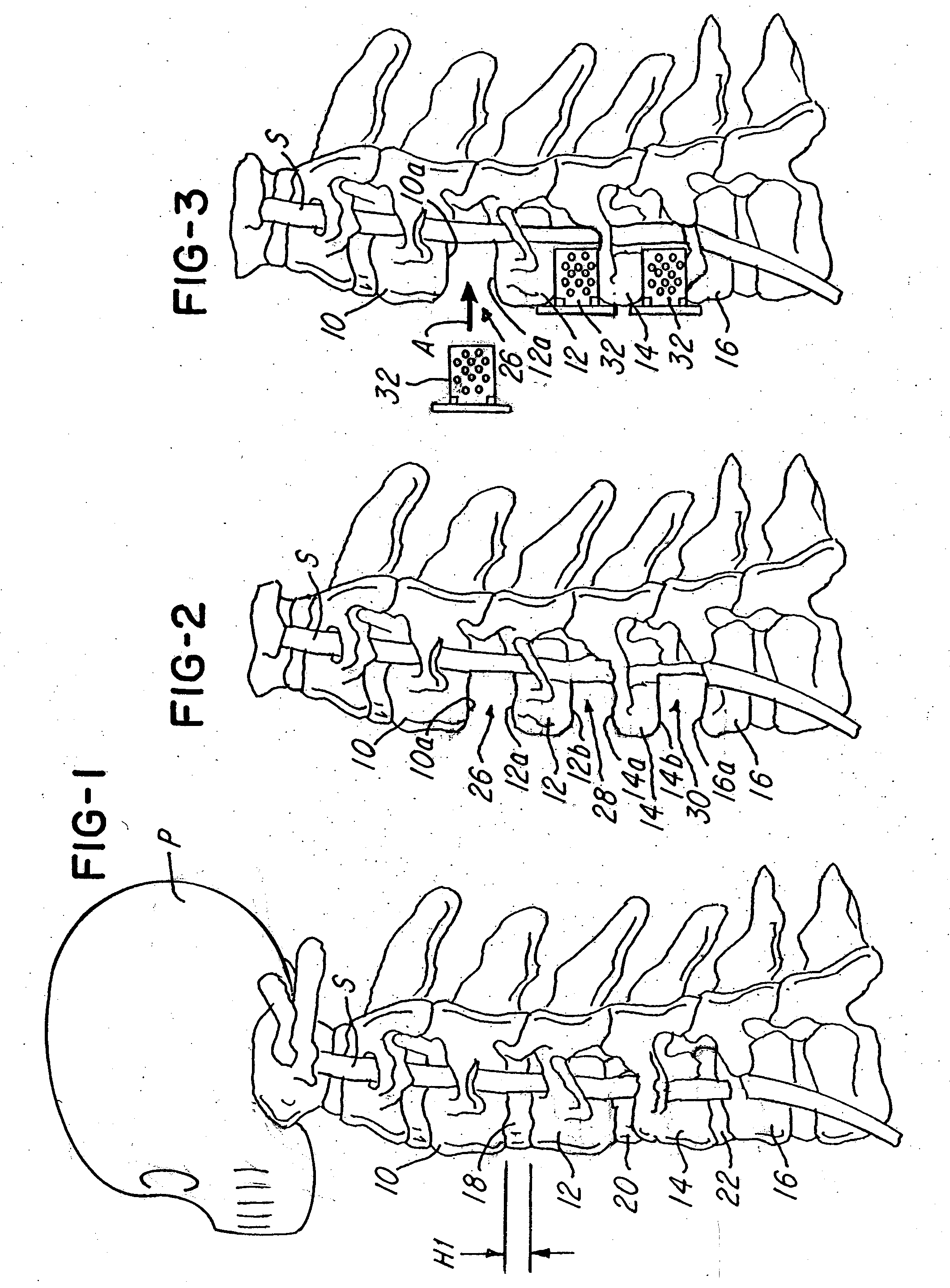
[0065] Referring now to FIG. 1, a partial side view of a patient or person P is shown having a spinal column S and a plurality of spinal bones, such as vertebrae, 10, 12, 14 and 16. Note that a disc, such as discs 18, 20 and 22 in FIG. 1, is located between adjacent pairs of spinal bones (e.g., between bones 10 and 12, 12 and 14, and 14 and 16). During a spinal fusion procedure, such as a discectomy, the discs 18, 20 and 22 may be removed so that adjacent vertebrae may be fused together

[0066]FIG. 2 illustrates a fragmentary view of the spinal column S shown in FIG. 1, with the discs 18, 20 and 22 removed. It should also be understood that during another surgical procedure, such as a vertebrectomy, it may be desired to remove part of all of one of the spinal bones 10-16, as illustrated in FIG. 13. In this type of neurological procedure, it may also be desired to fuse adjacent spinal bones together for reasons that are conventionally known. This invention provides means for facilitat...


PUM

PropertyMeasurementUnit
Flexibilityaaaaaaaaaa
Areaaaaaaaaaaa
Biocompatibilityaaaaaaaaaa

Abstract

Spinal fusion system utilizing an implant plate having at least one integral lock.

Description

RELATED APPLICATION DATA [0001] This application is a continuation-in-part of U.S. patent application Ser. No. 10 / 858,629, filed Jun. 2, 2004, which is a continuation-in-part of U.S. patent application Ser. No. 10 / 675,361, filed Sep. 30, 2003, both of which are incorporated herein by reference and made a part hereof.BACKGROUND OF THE INVENTION [0002] 1. Field of the Invention [0003] This invention relates to a veritable prosthetic system and device and a method for implanting the device and, more particularly, to a spinal fusion system and method for fusing spinal bones. [0004] 2. Description of the Related Art [0005] Many types of prosthetic devices have been proposed in the past. For example, U.S. Pat. No. 5,192,327 to Brantagan concerns a surgical prosthetic modular implant used singularly or stacked together to support and fuse together adjacent vertebrae or to totally or partially replace one or more vertebrae in a vertebral column. Other surgical implant devices and methods ar...

Claims


Application Information

Patent Timeline
IPC IPC(8): A61F2/30A61B17/70A61B17/80A61B17/86A61F2/00A61F2/02A61F2/28A61F2/44F16B35/06
CPCA61B17/7059A61B17/8042A61B17/8047A61B17/8052A61B17/8605A61F2/30744A61F2/44A61F2/4465A61F2/447A61F2002/2835A61F2002/30062A61F2002/30131A61F2002/30383A61F2002/30385A61F2002/30398A61F2002/30439A61F2002/305A61F2002/30505A61F2002/30507A61F2002/30517A61F2002/30576A61F2002/30578A61F2002/30604A61F2002/30616A61F2002/30784A61F2002/30785A61F2002/30794A61F2002/30904A61F2002/4475A61F2002/449A61F2210/0004A61F2220/0025A61F2220/0041A61F2230/0013A61F2310/00017A61F2310/00023A61F2310/00161A61F2002/30433A61F2002/30593A61F2002/3079
Inventor KIRSCHMAN, DAVID LOUIS
Owner X SPINE SYST
Why Eureka
Try Eureka