

Ultrasonic cutting device
- Summary
- Abstract
- Description
- Claims
- Application Information
AI Technical Summary
Benefits of technology
Problems solved by technology
Method used
Image

Examples
Embodiment Construction
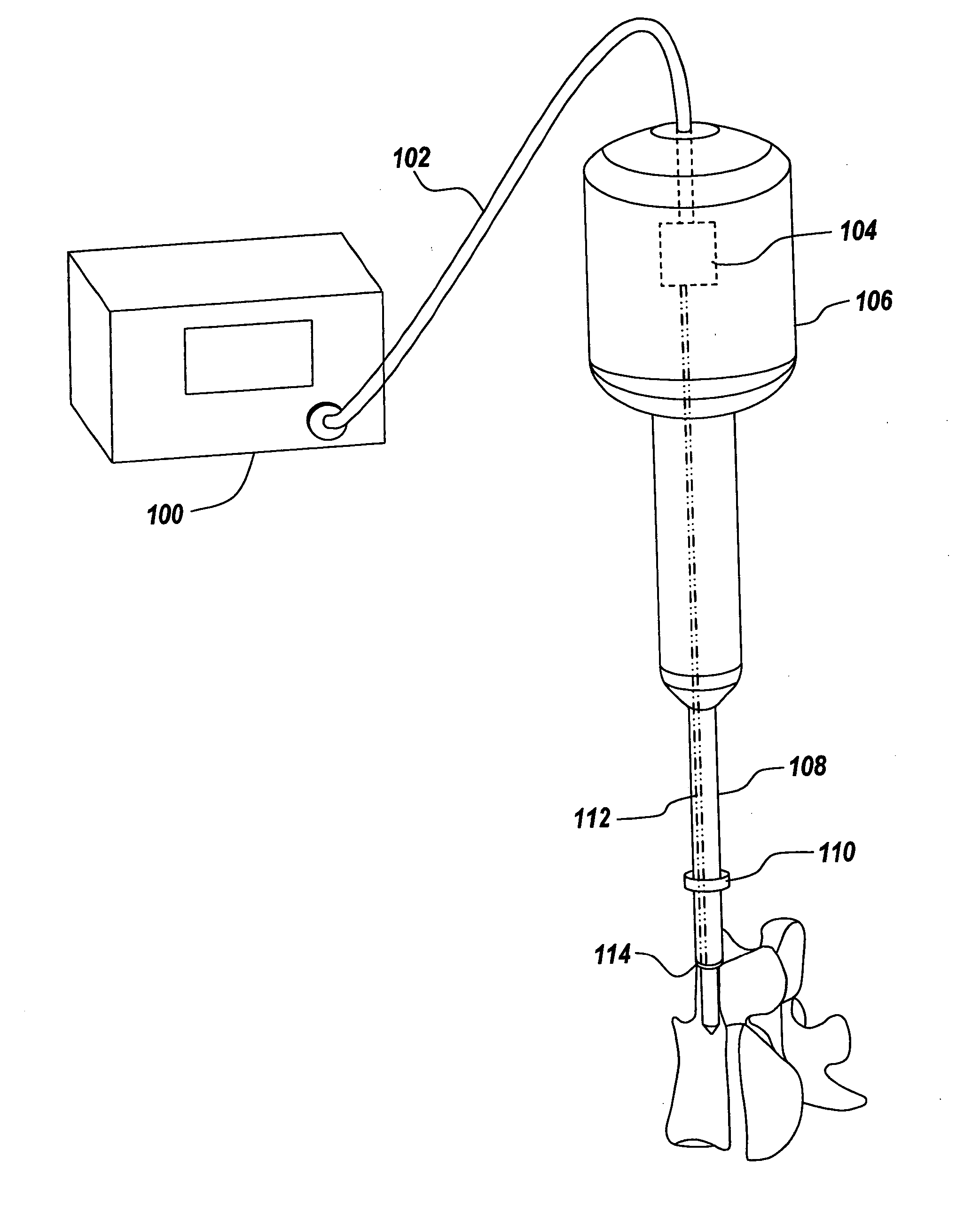
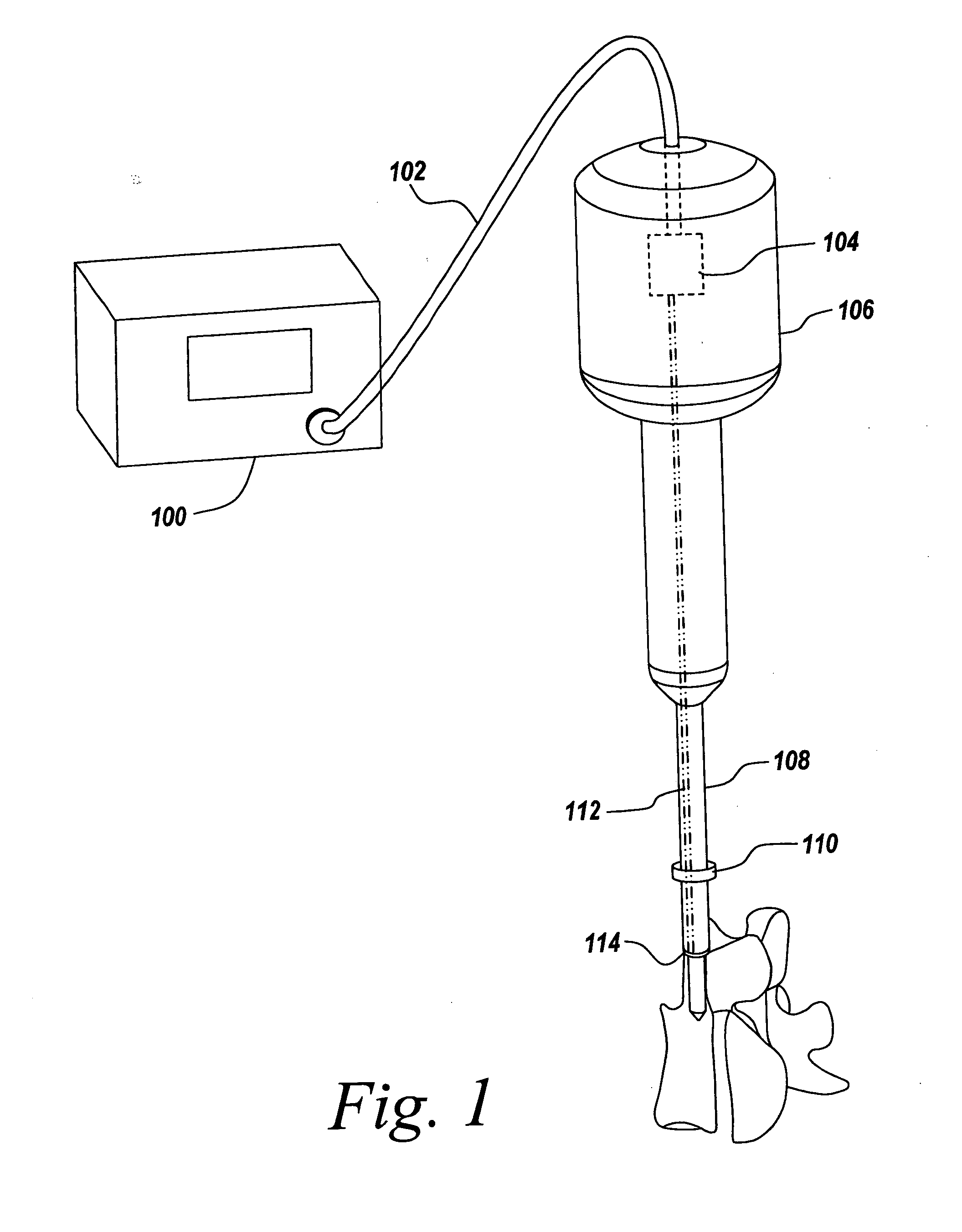
[0022] The present invention generally relates to an ultrasonic surgical cutting system, wherein a lateral cutter is used to cut through hard tissue such as bone, while simultaneously preventing unintended damage to tissue adjacent to the intended tissue to be cut. Additionally, the present invention provides for cutting of an intended material using a lateral cutter, wherein the lateral cutter has a reduced temperature. Because the device employs a cooled cutter arrangement, inherent problems of ultrasonic cutting instruments are reduced. For example, using a cooled cutter arrangement coupled with a low initial amplitude, bone may be cut in a manner such that necrosis does not develop. Additionally, while cutting a hard tissue such as bone, should the cooled cutter contact surrounding soft tissue, damage to the soft tissue will not result. Furthermore, coupled with an increase in amplitude to cut soft tissue, the cutter's temperature is reduced so that soft tissue cut by the presen...
PUM
 Abstract
Description
Claims
Application Information