Arrangement in connection with unmanned mine vehicle

a mine vehicle and arrangement technology, applied in the direction of process and machine control, distance measurement, instruments, etc., can solve the problems of difficult and expensive construction of control systems capable of extremely accurate stopping in demanding mine conditions, easy to become complex, and sensitive to failures, etc., to achieve simple implementation, reliable system, and relatively simple monitoring of wheel speed

a mine vehicle and arrangement technology, applied in the direction of process and machine control, distance measurement, instruments, etc., can solve the problems of difficult and expensive construction of control systems capable of extremely accurate stopping in demanding mine conditions, easy to become complex, and sensitive to failures, etc., to achieve simple implementation, reliable system, and relatively simple monitoring of wheel speed

US20060195237A1Active Publication Date: 2006-08-31SANDVIK MINING & CONSTR OY

Image

  • Arrangement in connection with unmanned mine vehicle
  • Arrangement in connection with unmanned mine vehicle
  • Arrangement in connection with unmanned mine vehicle

Examples


Embodiment Construction

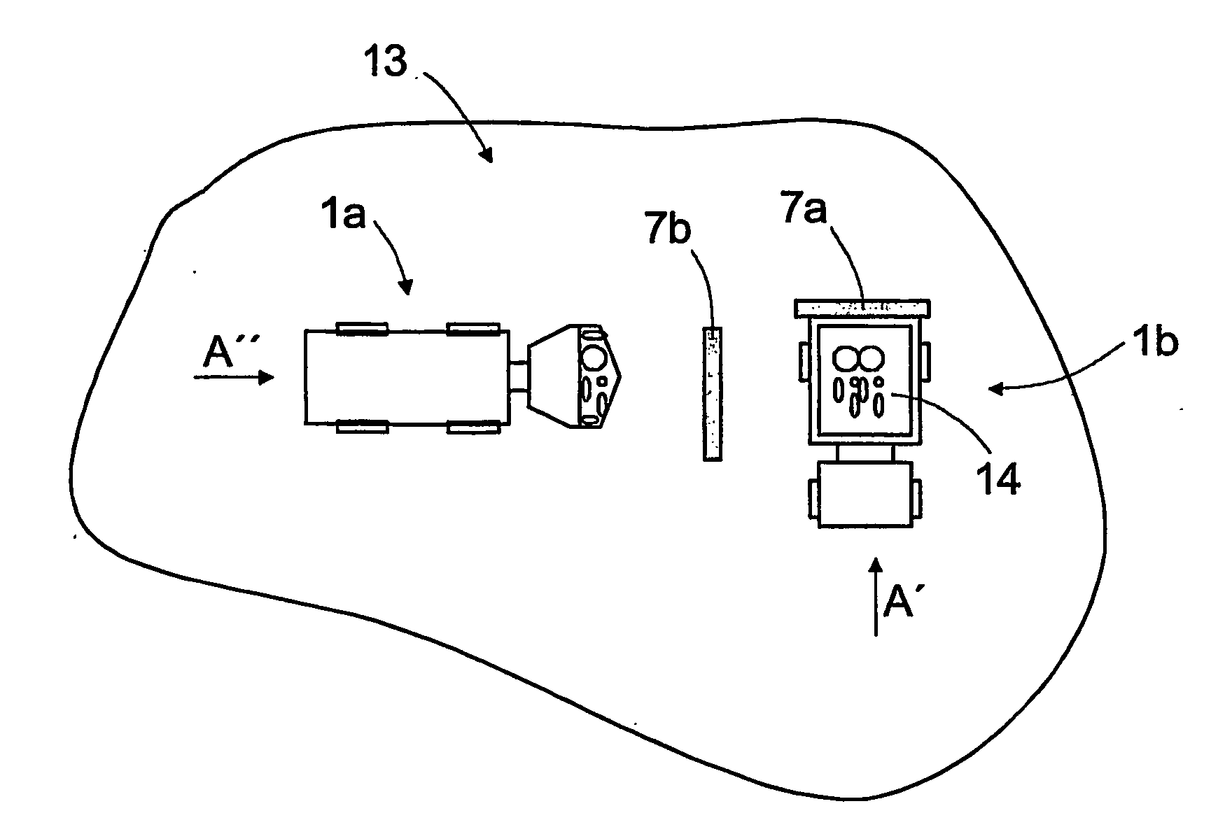
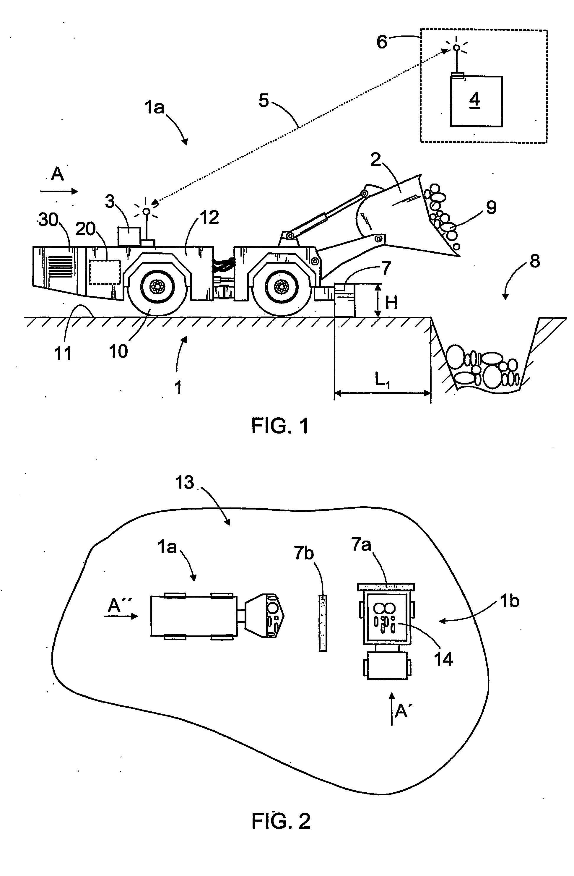
[0021]FIG. 1 shows an unmanned mine vehicle 1, in this case a loading vehicle 1a, which is a kind of wheel loader, there being a bucket 2 in its front part, with which crushed material can be transported from one place to another and loaded to other transport means, such as conveyors and transport vehicles 1b. The mine vehicle 1 comprises a first control unit 3, which is in connection with an outside second control unit 4 by means of a data transmission connection 5. The second control unit 4 may be arranged for instance in a monitoring room 6 outside the mine. Both the first control unit 3 and the second control unit 4 may be computers, in which computer programs intended for controlling the mine vehicle can be run. The data transmission connection 5 between the control units 3 and 4 may be either wired or wireless.

[0022] In FIG. 1, the loading vehicle 1a is stopped against an obstacle 7, at an appropriate distance from a pass chute 8, in which the bucket 2 of the loading vehicle ...


PUM


Abstract

A method and system for stopping an unmanned mine vehicle in a predetermined position. The mine vehicle is driven at a low speed towards a physical. When the mine vehicle encounters the obstacle (7, 7a, 7b), a speed difference greater than a predetermined limit value is generated between the speed of the mine vehicle and the driving power transmission. The control system of the mine vehicle detects the exceeding of the limit value and stops the vehicle.

Description

FIELD OF THE INVENTION [0001] The invention relates to a method of stopping an unmanned mine vehicle in a predetermined position, the mine vehicle being controlled by means of a control system comprising at least a first control unit in the mine vehicle, a second control unit outside the mine vehicle and a data transmission connection between said control units, and the method comprising: driving the mine vehicle, controlled by its control system, towards a predetermined position; and monitoring at least the speed of the mine vehicle and the speed of the driving power transmission of the mine vehicle. [0002] Further, the invention relates to a system for stopping an unmanned mine vehicle in a predetermined position, the system comprising: at least a control unit including at least a first control unit in the mine vehicle; a second control unit outside the mine vehicle and a data transmission connection between said control units; and means for monitoring the speed of the mine vehicl...

Claims


Application Information

Patent Timeline
31 Aug 2006
Publication
US20060195237A1
IPC
G06F7/70; G06F19/00; B60T7/22
CPC
B60T7/22
Inventors
MAKELA, HANNU