
Filtered exhaust system for commode

a commode and filter technology, applied in the field of improved, can solve the problems of cumbersome filter replacement, significant drawbacks, and insufficient location and use of charcoal filters inside the fan housing, and achieve the effect of convenient service and containment and easy replacemen

Inactive Publication Date: 2006-09-07
KIRBY DAVID
View PDF24 Cites 4 Cited by
  • Summary
  • Abstract
  • Description
  • Claims
  • Application Information

AI Technical Summary

Benefits of technology

[0012] This arrangement results in air that is filtered before passing into the remaining working parts of the system. This prevents any fan or blower and related hosing and circuitry from being contaminated by the noxious air drawn from the commode. The apparatus uses a filter which is unitized separate from the collection and flow inducement, which makes it easily serviced and contained for sanitary purposes. The filter unit can be easily changed without any contact or undue exposure to the filtering matrix within the filter unit.

Problems solved by technology

Although the Lee device is very useful, it also features some significant drawbacks.
Specifically, the location and use of a charcoal filter inside a fan housing is not optimum.
Changing the filter will be cumbersome and require an individual to come into physical contact with the used filter.
Furthermore, since the location of the filter is downstream of the fan, the fan blades will be fouled by the unpleasant air stream making it unpleasant during a filter changing operation.
However, installation of a system like this requires more extensive construction costs than many homeowners will endure.
While certainly novel, the use of an incineration device next to the commode will not be acceptable to many consumers.
While many of these systems are impressive, utilizing these systems requires replacing or severely altering the water tank of the commode.
This compromises or eliminates the use of the system in a retrofit manner, as many conventional water tanks for commodes cannot be easily adapted to incorporate these odor removing and filtering systems.
None of the prior art patents adequately accomplish these goals.

Method used


Image

  • Filtered exhaust system for commode
  • Filtered exhaust system for commode
  • Filtered exhaust system for commode

Examples


Embodiment Construction

[0025] The detailed description below is for preferred embodiments and is intended to explain the current invention. It is to be understood that a variety of other arrangements are also possible without departing from the spirit and scope of the invention.

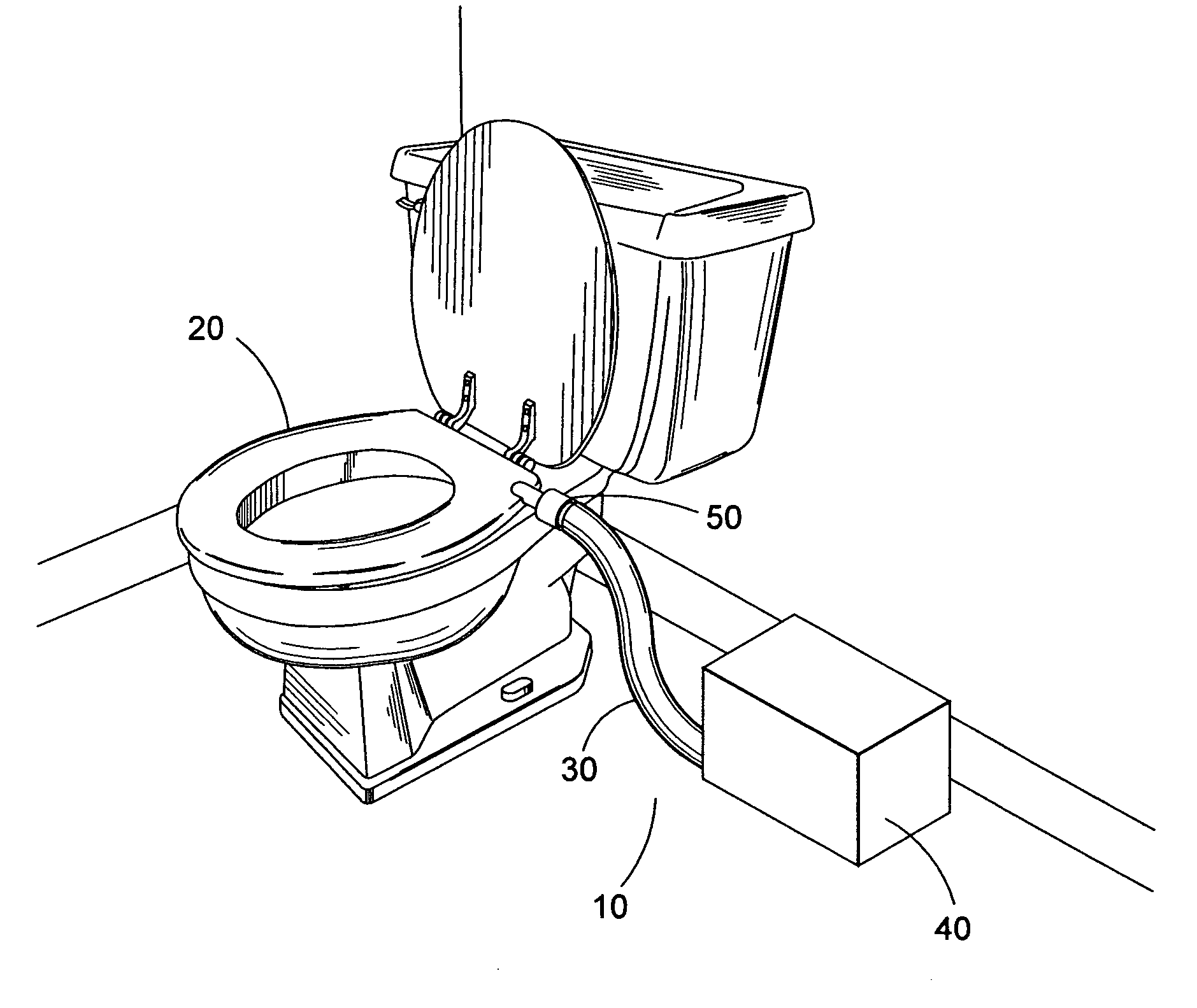
[0026]FIG. 1 shows an overview of the toilet ventilation system 10. This system comprises a toilet seat 20, a removable filter 30, and a means of inducing air flow, or fanbox 40. Toilet seat 20 is partially hollow having at least one entry point where air can be induced into and through toilet seat 20 and exit port 50 where filter 30 attaches. Filter 30 attaches at its other end into fanbox 40. Removable filter 30 is detachable at both ends, the end where it attaches to toilet seat 20 and the end where it attaches to fanbox 40. This is one of the major advantages of the system in that the entire filter 30 may be easily removed and disposed of and a new filter put in its place.

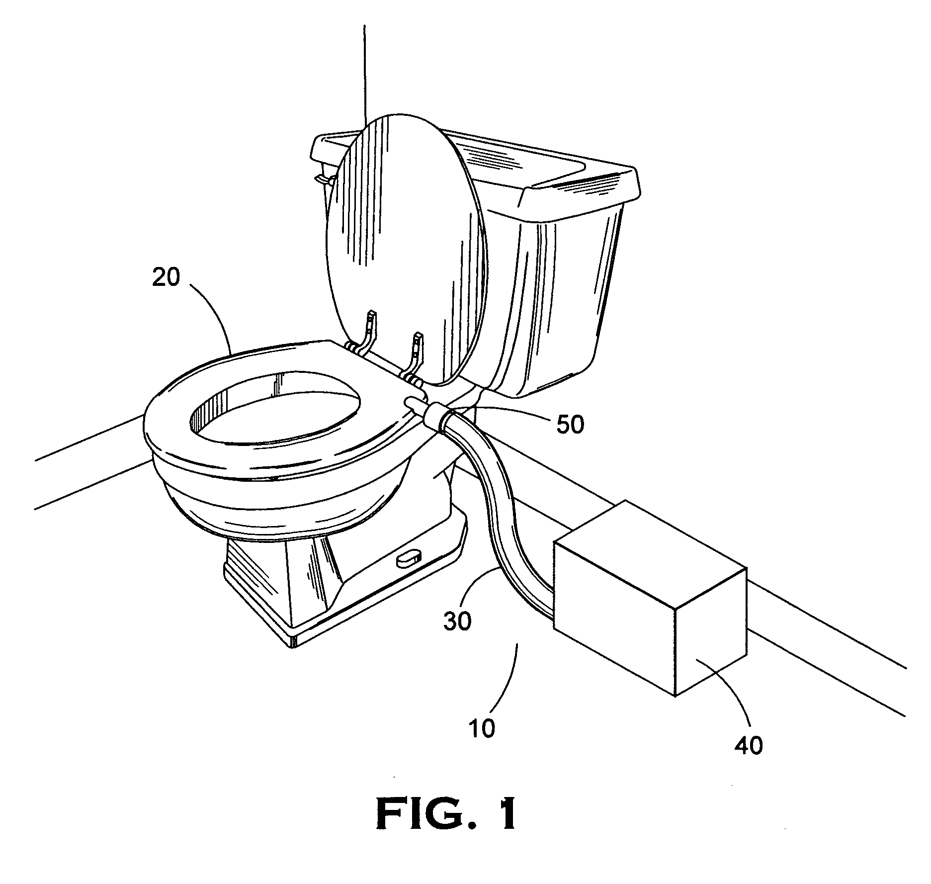
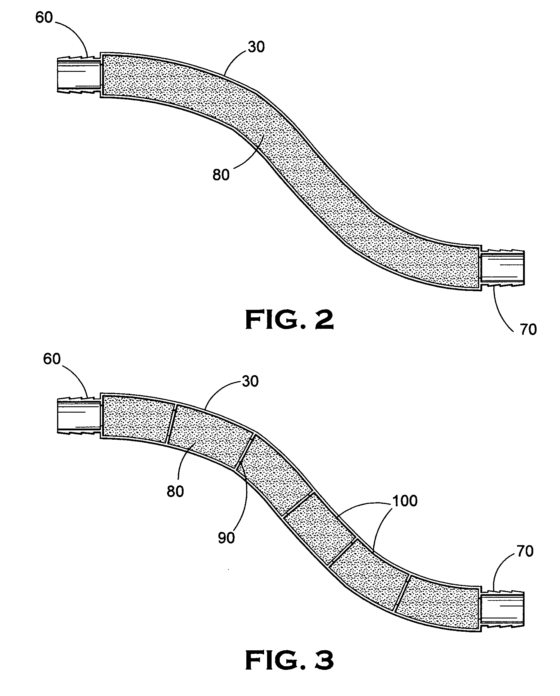
[0027] Referring now to FIGS. 2 and 3, cross-sections ...


PUM


Abstract

The apparatus of the present invention relates to exhausting noxious odors from the vicinity of a toilet. The invention comprises a means of taking in air from the vicinity of the toilet, a filter, and a means of inducing the air flow. The air is taken in by said means of taking in air, passed on to and through the filter, and then passed on to the means of inducing air flow. The air is then discharged from the system. The filter is separate and unitary and can be easily installed and removed without exposure of the filtering matrix within the filter. The contaminants entering the filter, i.e. bacteria and viruses, are killed and odorous gases are trapped in the filter. The person changing the filter is therefore not exposed to the possibility and vulgarity of contact with contaminants entrapped within a used filter when the change of the filter is needed.

Description

FIELD OF THE INVENTION [0001] This invention relates generally to an improved apparatus for exhausting noxious odors from the vicinity of a toilet commode during use, wherein an air vacuum system is incorporated into the commode seat, featuring a filtered hose which is easily removable and replaceable for treating the removed air. BACKGROUND OF THE INVENTION [0002] This invention addressed an age-old problem that has plagued mankind since the first indoor bathroom experience, namely the problem of dealing with noxious odors around the commode. Even though the bathroom experience is often a brief one, it is still unpleasant as the odors inherently created while using the bathroom are unpleasant for most people, and severely unpleasant for some. The problem is also compounded by the fact that bathrooms are frequently small, which serves to concentrate the odors in a very small area. In addition, unpleasant odors are also a problem in public restrooms, and bathroom users generally have...

Claims


Application Information

Patent Timeline
Patent Type & Authority Applications(United States)
IPC IPC(8): E03D9/04A47K13/00
CPCA47K13/307E03D9/052
Inventor KIRBY, DAVID
Owner KIRBY DAVID
Learn More