
Method of manufacturing liquid ejection head

a manufacturing method and liquid ejection technology, applied in the direction of variable capacitors, generators/motors, inking apparatus, etc., can solve the problems of complex piezoelectric body manufacturing process, difficult to form the bodies to a thickness of 30 m or below, and difficult processing of film thickness of a plurality of piezoelectric bodies, etc., to achieve reduced warping of the diaphragm, reduced manufacturing process, and reduced thickness

Inactive Publication Date: 2006-09-07
FUJIFILM CORP
View PDF4 Cites 1 Cited by
  • Summary
  • Abstract
  • Description
  • Claims
  • Application Information

AI Technical Summary

Benefits of technology

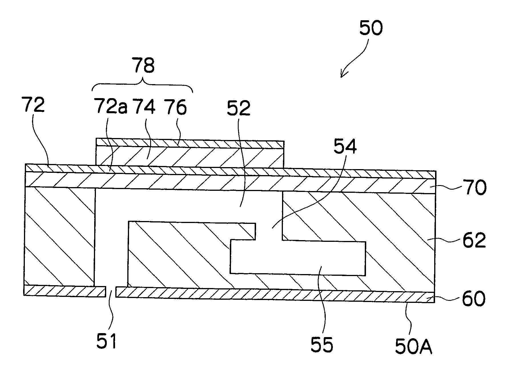
[0011] The present invention has been contrived in view of the foregoing circumstances, an object thereof being to provide a method of manufacturing a liquid ejection head comprising piezoelectric elements having good dimensional accuracy, by means of a simple manufacturing process.
[0013] According to the present invention, since the lower electrode, the undivided piezoelectric material and the undivided upper electrode are formed onto the whole surface of the substrate that is to form the diaphragm, and sandblasting is then performed through the mask having a prescribed pattern in order to simultaneously divide the piezoelectric material and the upper electrode, then the manufacturing process is simplified compared to a case where piezoelectric bodies and electrodes are formed individually by different methods at positions corresponding to the pressure chambers on the substrate, and furthermore, there is little variation or irregularity in the thickness due to divergence in the positions of the piezoelectric material and the upper electrodes, and hence the liquid ejection head having the piezoelectric elements with good dimensional accuracy can be manufactured. Furthermore, since the piezoelectric material and upper electrode are divided before calcining, the effects of thermal contraction in the piezoelectric material are distributed and warping of the substrate is reduced compared to a case where the members are divided after calcining.
[0014] Preferably, a hardness of the lower electrode is higher than a hardness of the upper electrode. According to this, by making the lower electrode of a material of the hardness higher than the hardness of a material of the upper electrode, then the lower electrode formed on the whole surface of the substrate, which is to be the diaphragm, can act as the blast stopping layer in the sandblasting process, and therefore it is possible to prevent deterioration of the diaphragm in the sandblasting process.
[0016] Preferably, the divided piezoelectric material and upper electrode have a substantially square planar shape and are arranged two-dimensionally. According to this, the piezoelectric material contracts in a substantially isotropic fashion during calcining, and therefore warping of the diaphragm is reduced further.
[0017] According to the present invention, since a lower electrode, a piezoelectric material and an upper electrode are formed onto the whole surface of a substrate that is to form a diaphragm, and sandblasting is then performed through a mask having a prescribed pattern in order to simultaneously divide the piezoelectric material and the upper electrode, then the manufacturing process is simplified compared to a case where piezoelectric bodies and electrodes are formed individually by different methods at positions corresponding to the pressure chambers on the substrate, and furthermore, there is little variation or irregularity in the thickness due to divergence in the positions of the piezoelectric material and the upper electrodes, and hence a liquid ejection head having piezoelectric elements with good dimensional accuracy can be manufactured. Furthermore, since the piezoelectric material and the upper electrode are divided before calcining, the effects of thermal contraction in the piezoelectric material are distributed and warping of the substrate is reduced compared to a case where the members are divided after calcining.

Problems solved by technology

In the method using bulk material, it is necessary to polish the bulk material in order to form the piezoelectric bodies as thin films; however, there are restrictions on handling and it is then difficult to form the bodies to a thickness of 30 μm or below.
On the other hand, in the method using screen printing, it is possible to form the piezoelectric bodies to a thin dimension; however, if it is attempted to print piezoelectric bodies onto positions corresponding to pressure chambers, through a screen, then there is a problem in that processing of the film thickness of a plurality of piezoelectric bodies is difficult, due to droop of the edge portions, and the like.
In other words, the lower and upper electrodes and the piezoelectric bodies are formed by different methods at the positions on the substrate corresponding to the pressure chambers, and hence the manufacturing process of the piezoelectric elements is complicated.
Moreover, positional divergence between the lower electrodes, the piezoelectric bodies and the upper electrodes is liable to occur, and hence there is a risk of variations in the ejection performance, such as the volume and speed of flight, of the ink droplets ejected from the nozzles.
Furthermore, when the portions of the piezoelectric body not covered by the mask are removed by a sandblasting process, then the substrate on which the piezoelectric body is to be formed becomes the blast stopping surface, which receives and stops the blasted abrasive particles, and there is a risk that the substrate may be damaged and degraded by the abrasive particles.

Method used


Image

  • Method of manufacturing liquid ejection head
  • Method of manufacturing liquid ejection head
  • Method of manufacturing liquid ejection head

Examples


Embodiment Construction

General Composition of Inkjet Recording Apparatus

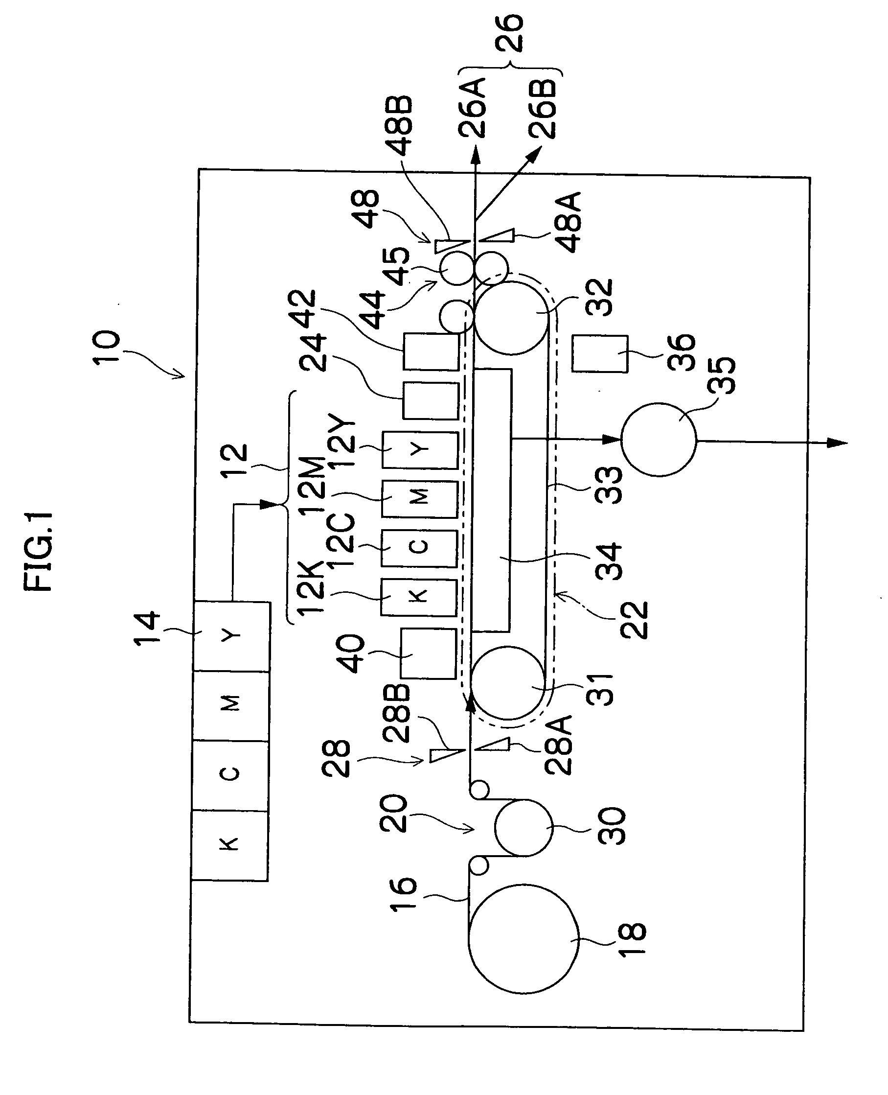
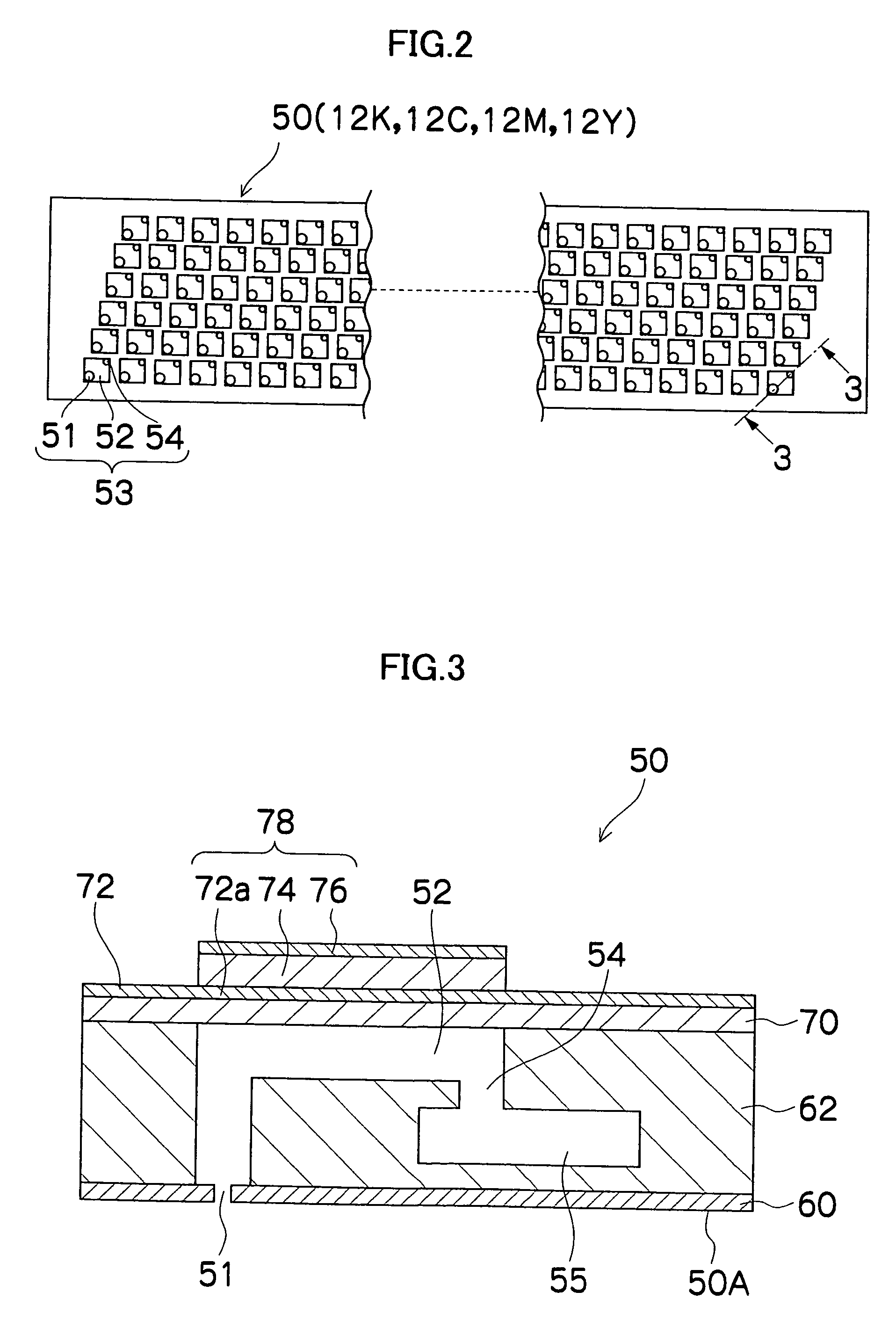
[0025]FIG. 1 is a general schematic drawing of an inkjet recording apparatus forming one embodiment of an image forming apparatus according to the present invention. As shown in FIG. 1, the inkjet recording apparatus 10 comprises: a printing unit 12 having a plurality of print heads 12K, 12C, 12M, and 12Y for ink colors of black (K), cyan (C), magenta (M), and yellow (Y), respectively; an ink storing and loading unit 14 for storing inks of K, C, M and Y to be supplied to the print heads 12K, 12C, 12M, and 12Y; a paper supply unit 18 for supplying recording paper 16; a decurling unit 20 for removing curl in the recording paper 16; a suction belt conveyance unit 22 disposed facing the nozzle face (ink-droplet ejection face) of the print unit 12, for conveying the recording paper 16 while keeping the recording paper 16 flat; a print determination unit 24 for reading the printed result produced by the printing unit 12; and a paper outpu...


PUM

PropertyMeasurementUnit
thicknessaaaaaaaaaa
Young's modulusaaaaaaaaaa
thicknessaaaaaaaaaa

Abstract

The method manufactures a liquid ejection head comprising: a plurality of nozzles which eject liquid; a plurality of pressure chambers which are connected to the nozzles, respectively; a diaphragm which forms wall faces of the pressure chambers; and piezoelectric elements which are disposed on the diaphragm at positions corresponding to the pressure chambers and each are formed of at least a piezoelectric material and electrodes overlapping each other. The method comprises the steps of: forming a lower electrode on a whole surface of a substrate that is to form the diaphragm; then forming piezoelectric material by screen printing onto a whole surface of the lower electrode; then forming an upper electrode on a whole surface of the piezoelectric material; then forming a mask having a prescribed pattern on the upper electrode; then dividing the piezoelectric material and the upper electrode by performing a sandblasting process through the mask; and then calcining the substrate together with the divided piezoelectric material and upper electrode.

Description

BACKGROUND OF THE INVENTION [0001] 1. Field of the Invention [0002] The present invention relates to a method of manufacturing a liquid ejection head, and more particularly, to a method of manufacturing a piezoelectric type liquid ejection head. [0003] 2. Description of the Related Art [0004] An image forming apparatus, such as an inkjet printer, is known which comprises a piezoelectric type print head (liquid ejection head) that ejects ink droplets from nozzles by applying pressure to ink accommodated in pressure chambers, through changing the volume of the pressure chambers by means of the displacement of piezoelectric elements. [0005] In recent years, there have been demands for improved image quality in the images formed by image forming apparatuses of this kind. For this purpose, it is necessary further to reduce the size of the ink droplets ejected from the nozzles of the print head, and to increase the density of the nozzles (to achieve high integration), and consequently, th...

Claims


Application Information

Patent Timeline
Patent Type & Authority Applications(United States)
IPC IPC(8): H04R17/00B41J2/135B41J2/14B41J2/145B41J2/16
CPCH04R17/00Y10T29/435Y10T29/42Y10T29/43B41J2/161B41J2/1632B41J2/1631B41J2202/03B41J2/1623B41J2/1646
Inventor MITA, TSUYOSHI
Owner FUJIFILM CORP
Learn More