Fuel supply apparatus for vehicle

a technology for fuel supply apparatus and vehicle, which is applied in the direction of fuel injecting pump, machine/engine, electric control, etc., can solve problems such as fuel pressure variations

Inactive Publication Date: 2006-09-07
TOYOTA JIDOSHA KK
View PDF11 Cites 10 Cited by
  • Summary
  • Abstract
  • Description
  • Claims
  • Application Information

AI Technical Summary

Benefits of technology

[0025] The foregoing and other objects, features, aspects and advantages of the present invention will become more apparent

Problems solved by technology

When a pressure attenuation mechanism such as the fuel filter is provided at the high-pressure fuel supply system as in the configuration disclosed in Patent Doc

Method used


Image

  • Fuel supply apparatus for vehicle
  • Fuel supply apparatus for vehicle
  • Fuel supply apparatus for vehicle

Examples


Embodiment Construction

[0030] Hereinafter, an embodiment of the present invention will be described in detail with reference to the drawings. In the following, the same or corresponding portions in the drawings have the same reference characters allotted, and detailed description thereof will not be repeated where appropriate.

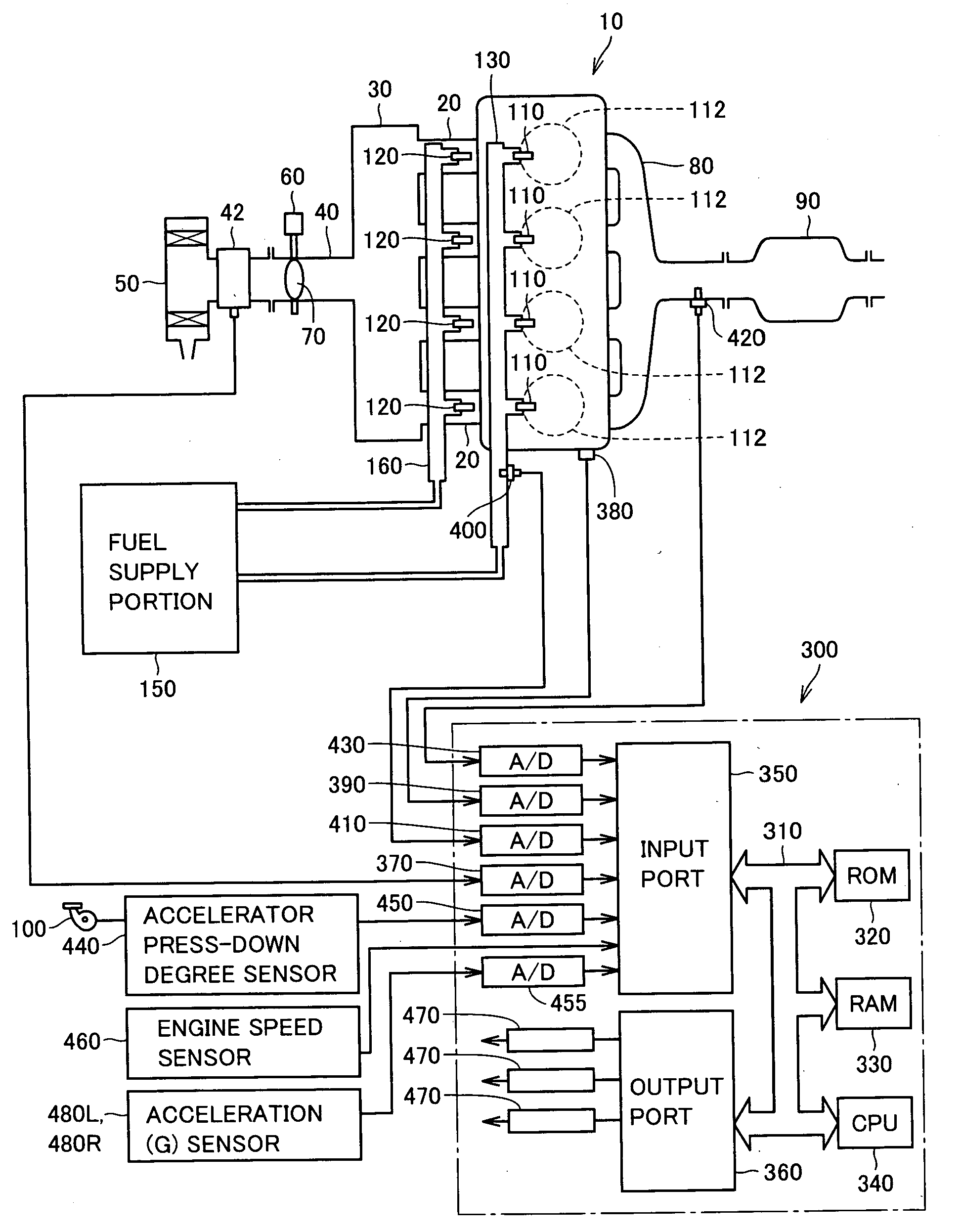
[0031]FIG. 1 schematically shows an engine system incorporating a fuel supply apparatus according to an embodiment of the present invention. Although an in-line 4-cylinder gasoline engine is shown in FIG. 1, application of the present invention is not restricted to the engine shown.

[0032] As shown in FIG. 1, the engine (internal combustion engine) 10 includes four cylinders 112, which are connected via corresponding intake manifolds 20 to a common surge tank 30. Surge tank 30 is connected via an intake duct 40 to an air cleaner 50. In intake duct 40, an airflow meter 42 and a throttle valve 70, which is driven by an electric motor 60, are disposed. Throttle valve 70 has its degree ...


PUM


Abstract

Fuel pipes guide fuel from a fuel tank provided in a rear area of the vehicle to a low-pressure fuel supply system and a high-pressure fuel supply system, respectively, for injecting the fuel to an engine provided in a front area of the vehicle. A branch point between the fuel pipes is arranged in the vicinity of the fuel tank to secure a long pipe length between the low-pressure fuel supply system and the high-pressure fuel supply system. This can suppress variation in fuel pressure at the low-pressure fuel supply system attributable to the fuel that is discharged from the high-pressure fuel pump within the high-pressure fuel supply system back to the fuel pipe.

Description

[0001] This nonprovisional application is based on Japanese Patent Application No. 2005-057438 filed with the Japan Patent Office on Mar. 2, 2005, the entire contents of which are hereby incorporated by reference. BACKGROUND OF THE INVENTION [0002] 1. Field of the Invention [0003] The present invention relates to a fuel supply apparatus for a vehicle, and more particularly to a fuel supply apparatus for a vehicle provided with a plurality of fuel supply systems to an internal combustion engine. [0004] 2. Description of the Background Art [0005] As a configuration of an internal combustion engine, one having both an intake manifold injector for injecting fuel into an intake port and an in-cylinder injector for injecting fuel into a cylinder is known. In this internal combustion engine, fuel injection control is carried out by combining intake manifold injection using the intake manifold injector and in-cylinder direct injection using the in-cylinder injector in accordance with an ope...

Claims


Application Information

Patent Timeline
IPC IPC(8): F02M69/46
CPCF02D41/3094F02M59/102F02M59/366F02M63/0225F02M63/024F02M63/029F02M69/044F02M69/046F02M63/02F02M69/04F02M69/46
Inventor TOMODA, TERUTOSHITSUCHIYA, TOMIHISASAKAI, MITSUTO
Owner TOYOTA JIDOSHA KK
Why Eureka
Try Eureka