

Automotive ventilation apparatus and automotive ventilation method
a technology for ventilation apparatus and automobiles, applied in ventilation systems, domestic cooling apparatus, heating types, etc., can solve the problems of not achieving high cooling efficiency of the apparatus disclosed in the reference literature mentioned above, and achieve the effect of high cooling efficiency
- Summary
- Abstract
- Description
- Claims
- Application Information
AI Technical Summary
Benefits of technology
Problems solved by technology
Method used
Image

Examples
first embodiment
[0022] The following is an explanation of the automotive ventilation apparatus in the first embodiment, given in reference to FIGS. 1 through 6.
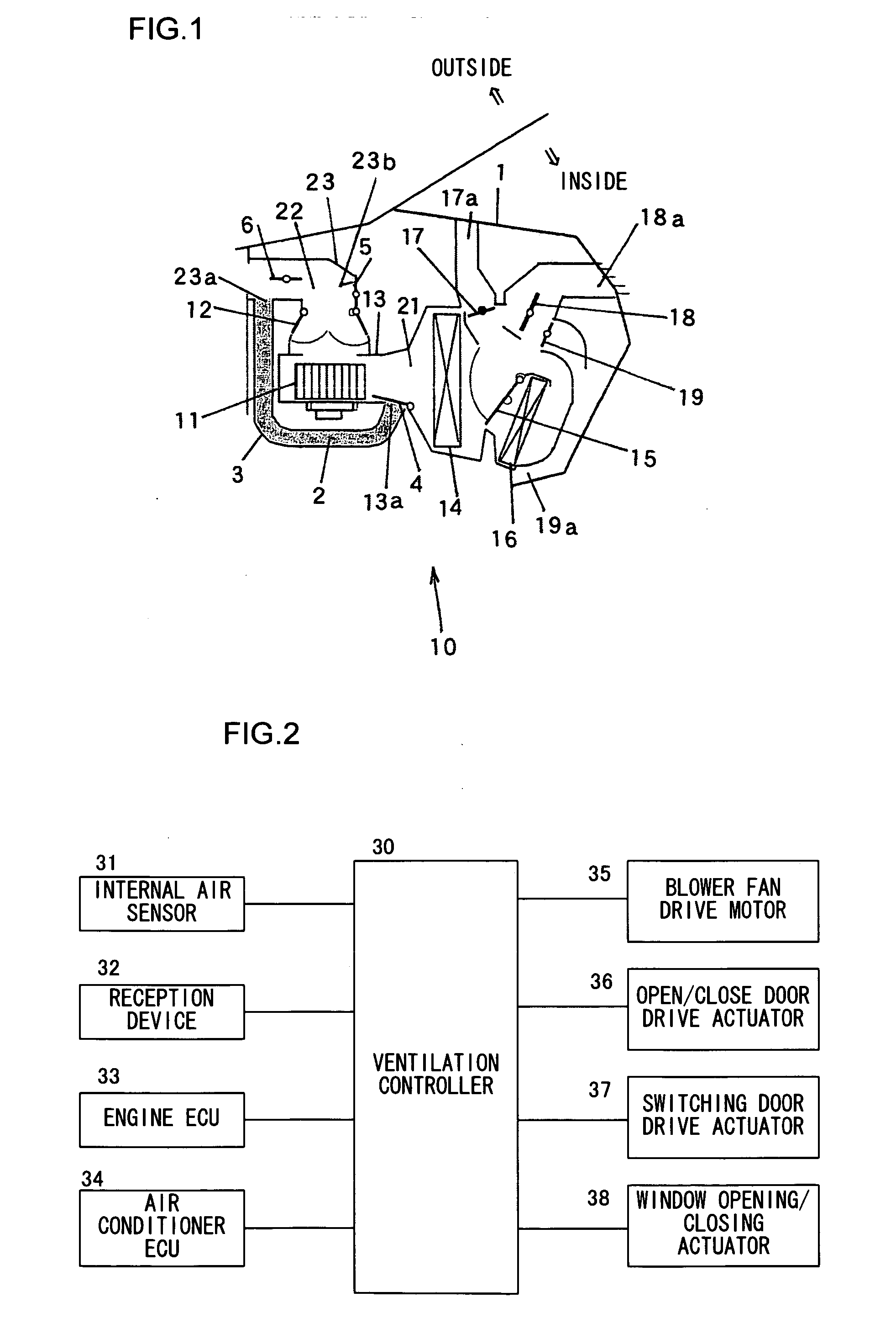
[0023]FIG. 1 schematically shows the structure adopted in the automotive ventilation apparatus in the first embodiment. An air-conditioning system 10 that controls the air condition inside the cabin is disposed inside an instrument panel 1 located at the front of the vehicle. The air-conditioning system 10 is utilized as a ventilation apparatus for ventilating the cabin while the vehicle is unoccupied.
[0024] The structure adopted in the air-conditioning system 10 is now explained. The air-conditioning system 10 includes a blower fan 11. As the blower fan 11 rotates, inside air or outside air is taken into an air-conditioning unit 13 via an inside air / outside air switching door 12. The air having been taken in is first cooled through an evaporator 14 and then passes through a heater core 16 at a rate corresponding to the degree of openness ...
second embodiment
[0062] In reference to FIGS. 7 and 8, the automotive ventilation apparatus in the second embodiment is explained.
[0063]FIG. 7 schematically shows the structure adopted in the automotive ventilation apparatus in the second embodiment. It is to be noted that the same reference numerals are assigned to components identical to those in FIG. 1. The following explanation focuses on components different from those in FIG. 1. The air discharge passage 2 in the automotive ventilation apparatus in the first embodiment is formed so as to extend from the downstream side of the blower fan 11 to the outside air intake passage 22. The automotive ventilation apparatus in the second embodiment further includes an air discharge passage formed to extend from a defogger duct 25 toward the air drawing duct 23.
[0064] As shown in FIG. 7, one end of a conduit member 41 is connected via a communication port 25a to the defogger duct 25 with the other end of the conduit member 41 connected to the air drawin...
third embodiment
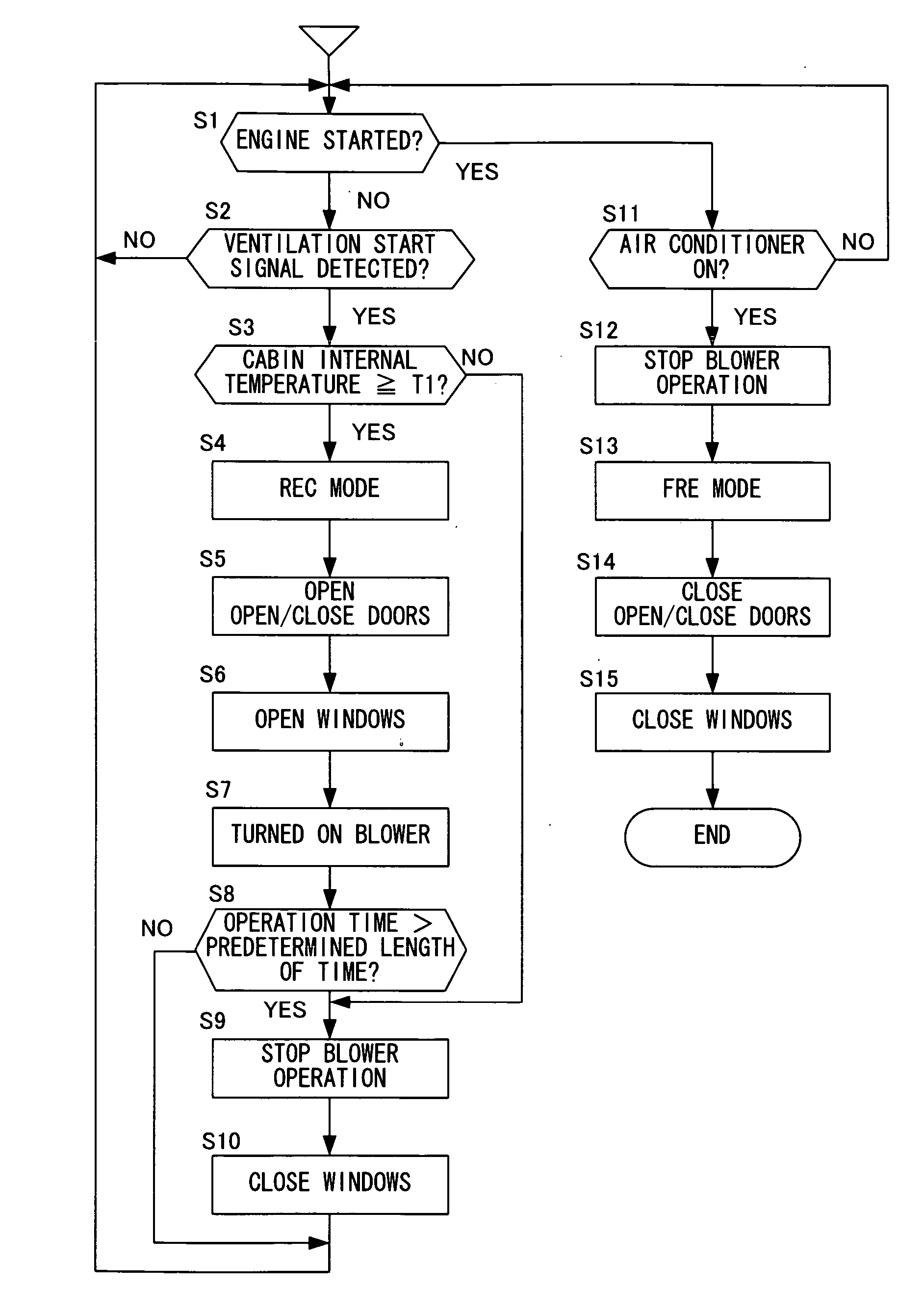
[0069] In reference to FIG. 9, the automotive ventilation apparatus in the third embodiment is explained.
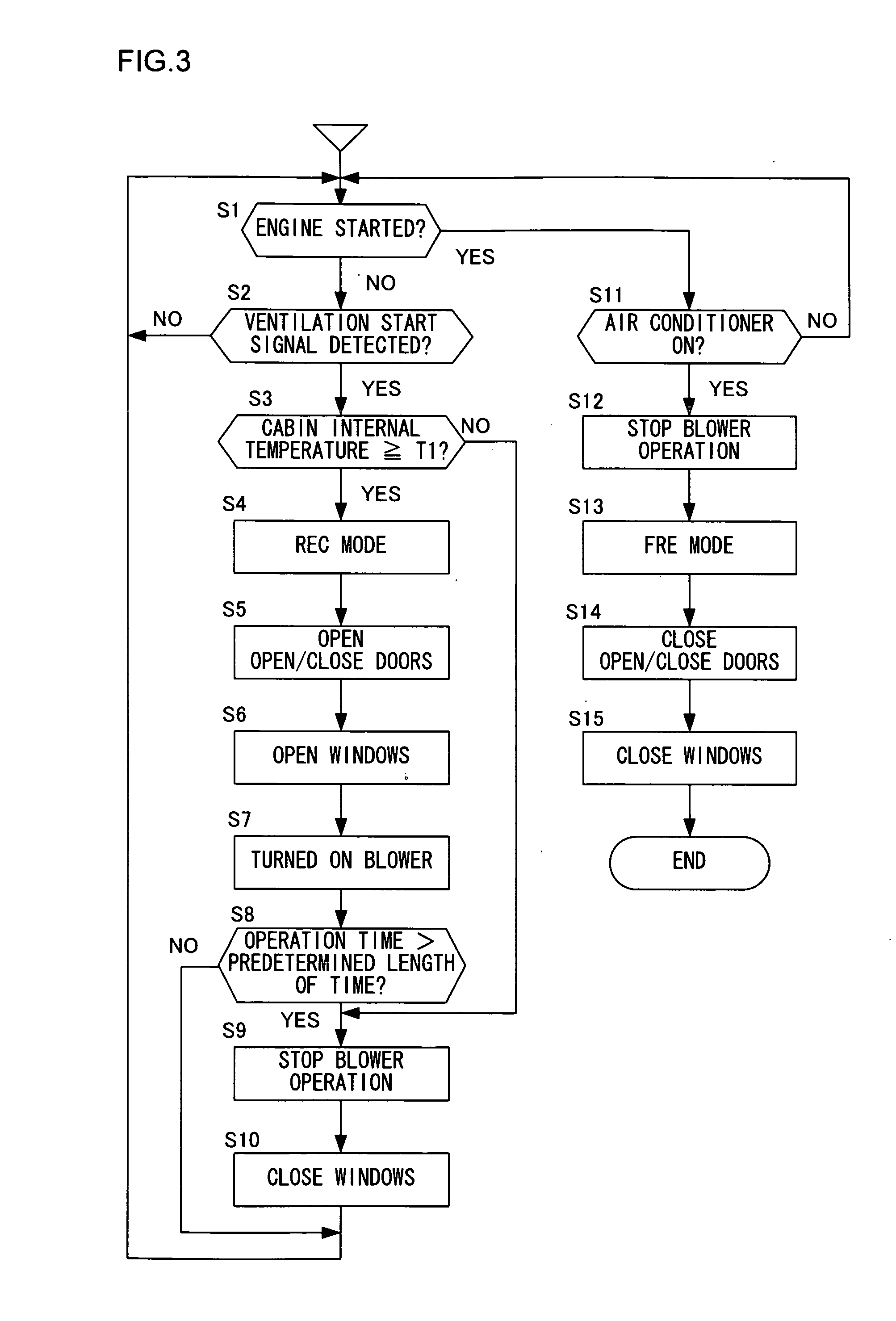
[0070] The following explanation focuses on the feature of the embodiment that differentiates it from the first embodiment. The automotive ventilation apparatus in the third embodiment differs from the automotive ventilation apparatus in the first embodiment in the processing executed by the ventilation controller 30. FIG. 9 presents a flowchart of an example of processing that may be executed by the ventilation controller 30 in the third embodiment. It is to be noted that the same step numbers are assigned to steps in which processing identical to that in FIG. 3 is executed.
[0071] After the open / close doors 4 and 5 are opened in step S5, the operation proceeds to step S7. In step S7, the blower fan 11 is turned on without opening the side windows 40. Once the blower fan 11 is engaged in operation, the operation proceeds to step S21.
[0072] In step S21, a decision is made as to...
PUM
 Abstract
Description
Claims
Application Information