Positioning method, apparatus and a product thereof

a technology of positioning method and positioning apparatus, applied in the direction of welding apparatus, laser beam welding apparatus, metal working apparatus, etc., can solve the problems of lagging or leading positional errors of the transport system of the substrate, and the reflection tracking of the laser can give rise to difficulties, etc., to achieve cost-effective effects

Inactive Publication Date: 2006-09-07
OERLIKON SOLAR AG (TRUEBBACH)
View PDF17 Cites 13 Cited by
  • Summary
  • Abstract
  • Description
  • Claims
  • Application Information

AI Technical Summary

Benefits of technology

[0020] datum positioning means enabling the working datum position to accord with local variations in thickness of the workpiece so that the working datum position is maintained at a fixed distance relative to a surface of the workpiece and / or
[0021] providing a carrier and transport system enabling the workpiece to be displaced along the path with the plane of the workpiece defined by the X-axis and the Y-axis either vertical or at some other angle to the horizontal.
[0032] Firstly by providing for the datum position of the laser beam to be linked to a Z-axis-tracking device which moves to automatically maintain a constant distance from the nearest substrate surface. This movement is conveyed to the focusing system for the laser to cause the datum position to be maintained effectively constant relative to the local substrate surface even if the local substrate thickness varies.
[0036] A fluidic unit can be arranged to provide for a cost effective process by using inert and non inert fluidising gases such as nitrogen, helium and oxygen. By establishing a closed circuit fluidic system the resulting machining process can provide for a closely controlled environment for the micromachining process concerned.

Problems solved by technology

Laser reflection tracking can give rise to difficulties arising from changes in transmission characteristics in the substrate material.
Transport systems for the substrate can give rise to lagging or leading positional errors caused by feedback delays.
Multi surface reflections or reflectivity changes can lead to locating errors.
Secondly by using ultra flat chucks to carry the substrate.
Ultra flat chucks are unable to take into account variations in thickness of the substrate.
Such chucks are inherently expensive to manufacture to sufficiently tight tolerances.

Method used


Image

  • Positioning method, apparatus and a product thereof
  • Positioning method, apparatus and a product thereof
  • Positioning method, apparatus and a product thereof

Examples


Embodiment Construction

[0055] Two new systems according to the present invention directed to accurate and reproducible positioning will now be outlined.
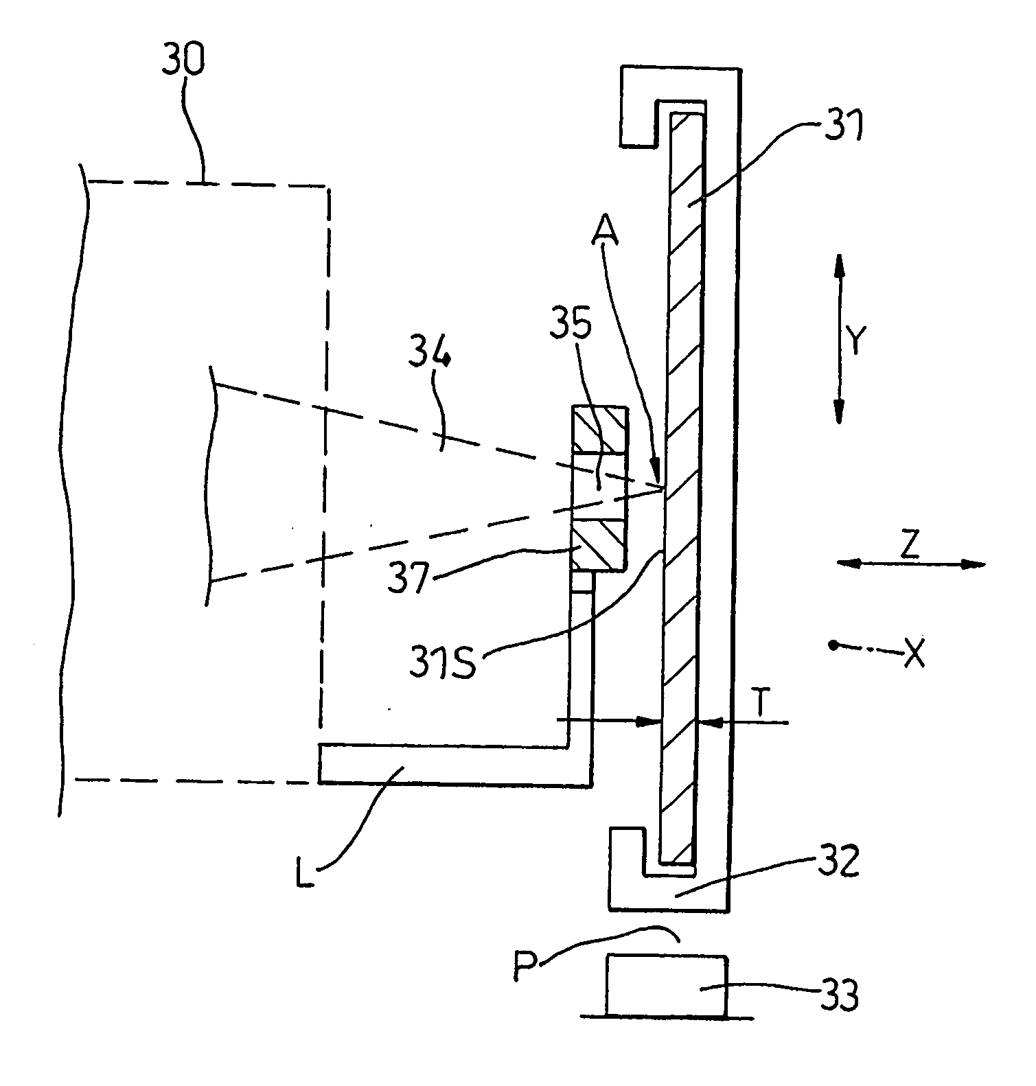
FIG. 3

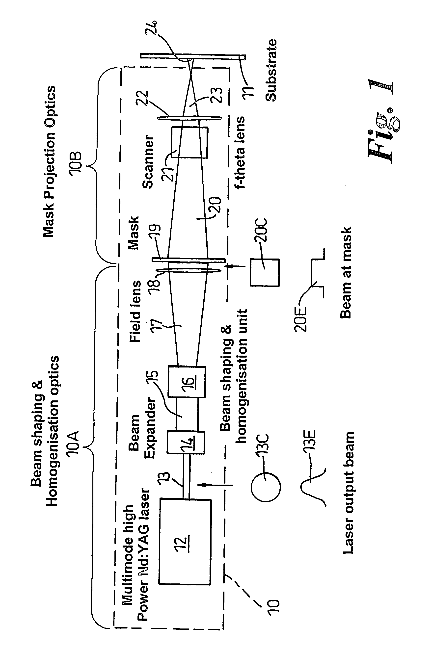
[0056] This shows diagrammatic output end 30 of a micro-machining unit with a workpiece 31 located on a carrier 32 (forming part of a workpiece transport system). The workpiece 31 can be displaced along a rail 33 in the direction of axis X (perpendicular to the plane of the drawing). In this case the laser beam 34, corresponding to beam 23 of FIG. 1, is focussed at datum position A to provide for the micro machining of, and through, first surface 31S of workpiece 31 by ablating predetermined regions of the workpiece 31. An air powered puck 37 is provided to automatically control the location of datum position A when required as will be described hereafter.

[0057] Ideally given that the work-piece 31 is of uniform thickness T; the carrier 32 is able to provide an steady progression along path P into the plane of the paper; and no relative lateral mot...


PUM

PropertyMeasurementUnit
distanceaaaaaaaaaa
thicknessaaaaaaaaaa
angleaaaaaaaaaa

Abstract

A method of laser micro-machining a work piece, with a laser, including the steps of: locating the workpiece on a carrier forming a part of a transport system, the carrier can be displaced along a path parallel to an X-axis of the workpiece, a Y-axis lying transverse the path, and a Z-axis lying transverse the path; focusing an image generated by an output beam from the laser at a working datum position defined relative to the path which path is established by the transport system to traverse the first datum position; a plane defined by the X- and Y-axis lying substantially perpendicular to the output beam; and displacing the workpiece along the path by way of the transport system so as to enable the work-piece to be subject to micro-machining by way of the laser.

Description

TECHNICAL FIELD [0001] This invention relates to a positioning method and apparatus and a product of the method or apparatus. In particular it is concerned with the positioning of a workpiece or substrate typically in the form of a plate or sheet of substantial size for accurate laser micro-machining applications. BACKGROUND ART [0002] Pulsed laser micro-machining techniques using mask projection methods are now widely used for the creation of miniature structures in both massive and thin substrates. Micro-electro-mechanical systems (or ‘MEMS’) are frequently prototyped by ‘excimer’ laser ablation of polymer substrates using motion of the substrate and / or a mask to create complex 2.5D and 3D structures. Typically sub-micron thick inorganic, metallic and organic films incorporated in, for example, solar panels, sensors and display devices are often patterned using mask projection methods with both solid state and gas laser sources. Over many years such processes have become well esta...

Claims


Application Information

Patent Timeline
Patent Type & Authority Applications(United States)
IPC IPC(8): B23K26/08B23K26/04
CPCB23K26/04B23K26/032B23K26/0648B23K26/0861B23K26/0622B23K2101/36
Inventor BANN, ROBERTSYKES, NEIL
Owner OERLIKON SOLAR AG (TRUEBBACH)
Why Eureka
Try Eureka