Apparatus, method and use for screening the magnetic field of an RFID transponder

a technology of magnetic field and rfid transponder, which is applied in waveguide devices, instruments, transmission, etc., can solve the problems of metallic surface, insufficient energy for electric excitation of transponder antennas, and sometimes reduced functionality of these devices, and achieves cost-effective production processes. , the effect of easy control

Active Publication Date: 2010-08-12
IDENTIV GMBH
View PDF6 Cites 9 Cited by
  • Summary
  • Abstract
  • Description
  • Claims
  • Application Information

AI Technical Summary

Benefits of technology

[0019]Moreover, the object is achieved by a use of an apparatus for screening the magnetic field of an RFID transponder, according to one of claims 1 to 13, for reducing functional losses of the RFID transponder caused by eddy current losses.
[0050]In an alternative embodiment, the strips are fixed on the carrier by means of a bonding agent or a lacquer. Such fixing means are inexpensive and easily available, thus allowing a relatively cost-effective production process which is addition is still easy to control.

Problems solved by technology

If, however, such RFID transponders are used as a substrate on metallically conductive surfaces, the functionality of these devices is sometimes reduced dramatically since, because of the magnetic fields used for communication between transponder and reader, eddy currents may be induced in the metallic material and also sometimes in the antenna structure, and as a result electric excitation of the transponder antenna cannot be carried out with sufficient energy.
Consequently, the resulting magnetic field on the metallic surface is weakened to such an extent that adequate energy supply of the transponder and data transfer become impossible.
Although this ensures the transponder's functional capability, the construction may sometimes represent a significant limitation due to the resulting overall height of transponder and spacer.
Moreover, the production costs for such spacers may also be far above the costs for the actual transponder and thus make this technology appear unattractive for many processes where high quantities are used.
The manufacture of such a ferrite film, however, places high demands on the homogeneity of the composite material and therefore results in relatively high costs for manufacture.
The device can only be attached to flat surfaces due to the stiffness.
High manufacturing costs and the thickness of the entire device additionally restrict the application range of this magnetic field screening.
Although the data exchange on metallic surfaces is improved with this positioning of the antenna, nevertheless the disadvantage which arises is again a large average distance between the antenna and the metallic surface and low mechanical stability of the data exchange tag.
In addition, due to activation by means of heat or UV light there may be adverse effects on and damage to the object on which the tag has been attached.
The overall process is complex and results in a brittle screen with limited flexibility.
Due to the printing process, the application is normally reduced to flat surfaces or makes it necessary to use a relatively complicated printing method.
The constantly parallel alignment of the particles to the induced magnetic field lines of the transponder requires expensive magnetisation units to generate complex magnetic fields in the case of complex antenna geometries.
Moreover, high-precision alignment during the lamination process is required for bonding of the transponder and screen in order to achieve parallelism between the magnetically induced transponder field and the aligned particles, which makes mass production considerably more difficult and consequently leads to higher costs for an end product.

Method used


Image

  • Apparatus, method and use for screening the magnetic field of an RFID transponder
  • Apparatus, method and use for screening the magnetic field of an RFID transponder
  • Apparatus, method and use for screening the magnetic field of an RFID transponder

Examples


second embodiment

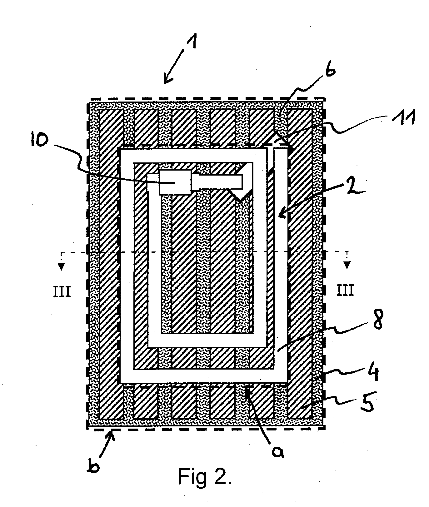
[0072]FIG. 4 illustrates magnetic field screen 1, whereby transponder 2 attached on magnetic field screen 1 corresponds to that from FIG. 2. The two-dimensional transponder again defines a first area section (a). The carrier in turn defines a second area section (b). The essential difference between magnetic field screen 1 shown here and that from FIG. 2 is in the transverse arrangement of strips 5 which are disposed laterally with corresponding clear areas 6 in a manner parallel to one another. A total of 10 strips 5 is provided in the embodiment of magnetic field screen 1 illustrated. It is significant in the present configuration, however, that if anisotropic permeability of the screening material is provided, the increased permeability of the screening material cannot run exclusively along the longitudinal edges of strip 5 and parallel to the visible surface. According to the invention, for example, increased permeability is then provided perpendicular to the longitudinal edges ...

third embodiment

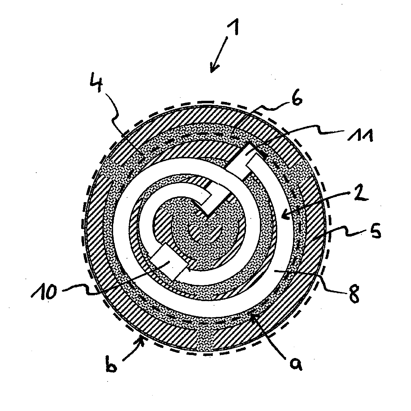
[0073]FIG. 5 illustrates magnetic field screen 1, whereby transponder 2 attached to magnetic field screen 1 again corresponds in its construction to that from FIG. 2. The central difference between magnetic field screen 1 shown here and that from FIG. 2 or FIG. 4 is in the wave-like shape of strips 5 which are disposed longitudinally in a manner parallel to one another on carrier 4 with corresponding clear areas 6. Provided in the embodiment illustrated in FIG. 5 are a total of 5 strips the number of which may, however, be changed at will according to the invention. It is significant in the present configuration that, if anisotropic permeability of the screening material is provided, for the execution according to the invention of magnetic field screen 1, a direction of increased permeability may not exclusively follow the wave structure of strips 5 but will, for example, essentially follow the orientation of the conductor tracks of antenna structure 8, said tracks running from top ...


PUM

PropertyMeasurementUnit
thicknessaaaaaaaaaa
frequencyaaaaaaaaaa
heightaaaaaaaaaa

Abstract

An apparatus for screening the magnetic field of a transponder is described, which apparatus comprises, in a first area section, at least one flat antenna structure which comprises conductor tracks for conducting current in a direction of current flow and has an application-specific extent, wherein the apparatus comprises a second area section or carrier to which strips of a highly permeable screening material are applied such that they are oriented with respect to one another in a predetermined manner, wherein the second area section is arranged parallel to the first area section. In order to effectively screen the magnetic field which is beamed in from the outside, for instance by a reader, and in order to effectively screen the magnetic field which is generated by the antenna structure of the transponder itself following excitation, and in order to reduce eddy current losses in a metal area arranged underneath, the highly permeable screening material has either anisotropic permeability, wherein increased permeability is provided in the direction of current flow, in particular in the direction of the conductor tracks of important sections of the antenna structure, or else provides for the strips to be oriented parallel to one another in important sections, wherein the longitudinal edges of the strips are provided in the direction of current flow, in particular in the direction of the conductor tracks of important sections of the antenna structure.

Description

RELATED U.S. APPLICATIONS[0001]Not applicable.STATEMENT REGARDING FEDERALLY SPONSORED RESEARCH OR DEVELOPMENT[0002]Not applicable.REFERENCE TO MICROFICHE APPENDIX[0003]Not applicable.FIELD OF THE INVENTION[0004]The invention relates to an apparatus for screening the magnetic field of an RFID transponder, in addition to a method for the manufacture of a screen for the magnetic field of an RFID transponder, and the use of an apparatus for screening the magnetic field of an RFID transponder in accordance with the preambles of claims 1, 2, 17, 18 and 32.BACKGROUND OF THE INVENTION[0005]The use of transponders, in particular of RFID transponders (radio frequency identification transponders), has already become widely accepted in countless areas of life and work. Due to the property of RFID transponders, in the following also referred to simply as transponders, of recording, processing and rereleasing information contactlessly via electromagnetic fields, they can contribute in a particula...

Claims


Application Information

Patent Timeline
Patent Type & Authority Applications(United States)
IPC IPC(8): H01Q1/52
CPCG06K19/07749Y10T29/49016G06K19/07771H04B5/0081
Inventor MIESLINGER, STEFANKOBER, MICHAEL
Owner IDENTIV GMBH
Why Eureka
Try Eureka