
Apparatus, method and use for screening the magnetic field of an RFID transponder
a technology of magnetic field and rfid transponder, which is applied in waveguide devices, instruments, transmission, etc., can solve the problems of metallic surface, insufficient energy for electric excitation of transponder antennas, and sometimes reduced functionality of these devices, and achieves cost-effective production processes. , the effect of easy control
- Summary
- Abstract
- Description
- Claims
- Application Information
AI Technical Summary
Benefits of technology
Problems solved by technology
Method used
Image

Examples
second embodiment
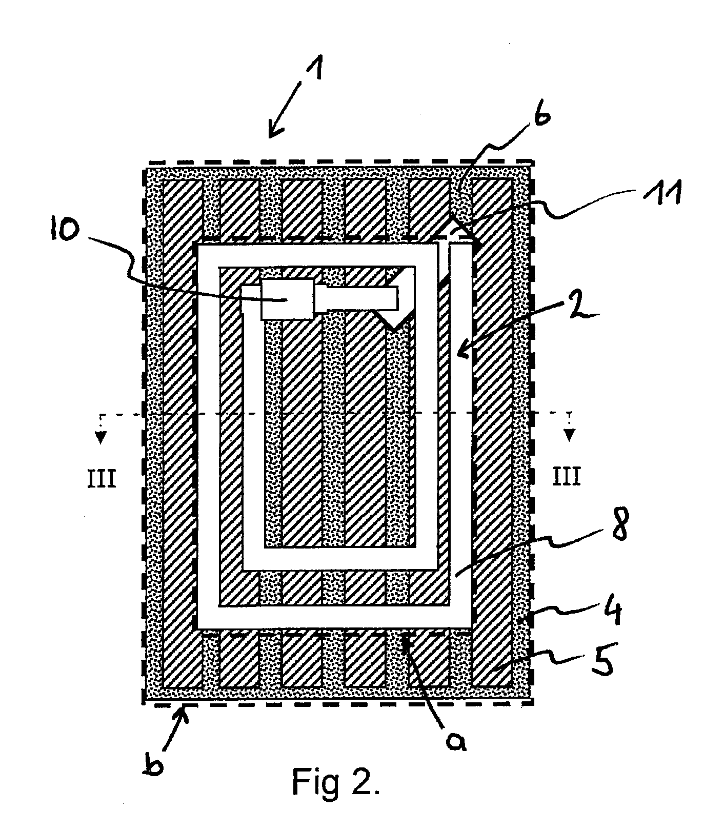
[0072]FIG. 4 illustrates magnetic field screen 1, whereby transponder 2 attached on magnetic field screen 1 corresponds to that from FIG. 2. The two-dimensional transponder again defines a first area section (a). The carrier in turn defines a second area section (b). The essential difference between magnetic field screen 1 shown here and that from FIG. 2 is in the transverse arrangement of strips 5 which are disposed laterally with corresponding clear areas 6 in a manner parallel to one another. A total of 10 strips 5 is provided in the embodiment of magnetic field screen 1 illustrated. It is significant in the present configuration, however, that if anisotropic permeability of the screening material is provided, the increased permeability of the screening material cannot run exclusively along the longitudinal edges of strip 5 and parallel to the visible surface. According to the invention, for example, increased permeability is then provided perpendicular to the longitudinal edges ...
third embodiment
[0073]FIG. 5 illustrates magnetic field screen 1, whereby transponder 2 attached to magnetic field screen 1 again corresponds in its construction to that from FIG. 2. The central difference between magnetic field screen 1 shown here and that from FIG. 2 or FIG. 4 is in the wave-like shape of strips 5 which are disposed longitudinally in a manner parallel to one another on carrier 4 with corresponding clear areas 6. Provided in the embodiment illustrated in FIG. 5 are a total of 5 strips the number of which may, however, be changed at will according to the invention. It is significant in the present configuration that, if anisotropic permeability of the screening material is provided, for the execution according to the invention of magnetic field screen 1, a direction of increased permeability may not exclusively follow the wave structure of strips 5 but will, for example, essentially follow the orientation of the conductor tracks of antenna structure 8, said tracks running from top ...
PUM
| Property | Measurement | Unit |
|---|---|---|
| thickness | aaaaa | aaaaa |
| frequency | aaaaa | aaaaa |
| height | aaaaa | aaaaa |
Abstract
Description
Claims
Application Information