Automated Molding Technology For Thermoplastic Injection Molding

a technology of injection molding and automatic molding, which is applied in the direction of auxillary shaping apparatus, manufacturing tools, ceramic shaping apparatus, etc., can solve the problems of increasing complexity of injection molding process, increasing cost, and increasing processing difficulty of engineering materials

Inactive Publication Date: 2006-09-07
AUTODESK INC
View PDF99 Cites 12 Cited by
  • Summary
  • Abstract
  • Description
  • Claims
  • Application Information

AI Technical Summary

Benefits of technology

[0013] An object of the present invention is to provide substantially automated optimization of at least a part of the injection molding set-up process

Problems solved by technology

As improved product quality and enhanced engineering properties are required of polymeric materials, the injection molding process has become increasingly complex: as service properties increase material processability tends to decrease.
Engineering materials are typically more difficult to process, and more expensive, and therefore their processing would benefit the most from automated molding optimization (AMO).
Injection molding is a batch operation, so machine set-up ultimately affects productivity.
It has been shown that under packing results in premature shrinkage, which may lead to dimensional variation and sink marks.
Over packing may cause premature opening of the tool (i.e. the die or mold of the component(s) to be manufactured) in a phenomenon known as

Method used


Image

  • Automated Molding Technology For Thermoplastic Injection Molding
  • Automated Molding Technology For Thermoplastic Injection Molding
  • Automated Molding Technology For Thermoplastic Injection Molding

Examples


Embodiment Construction

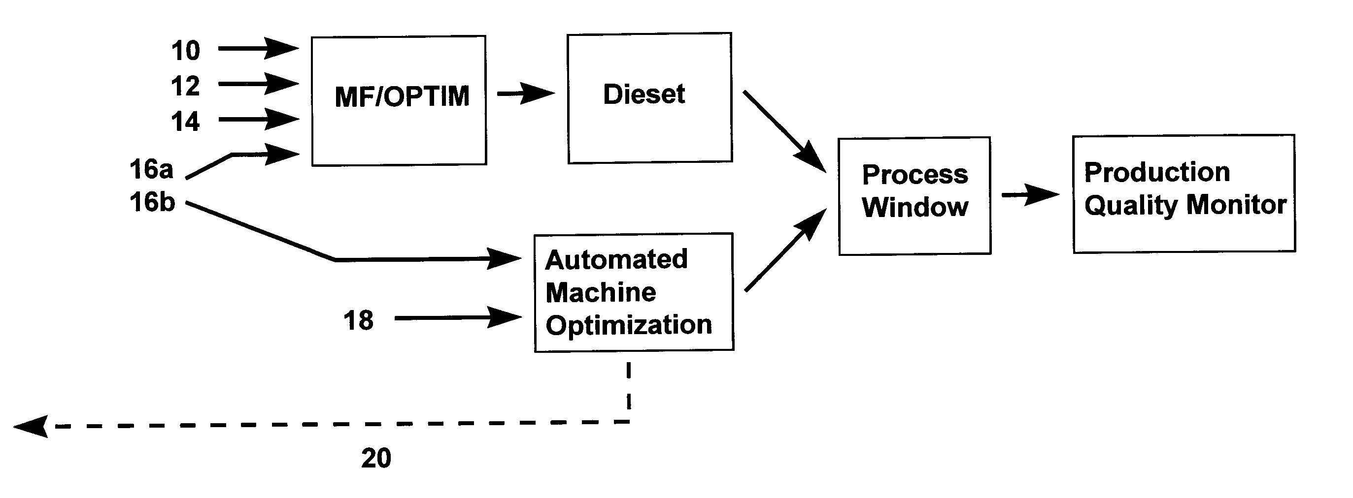
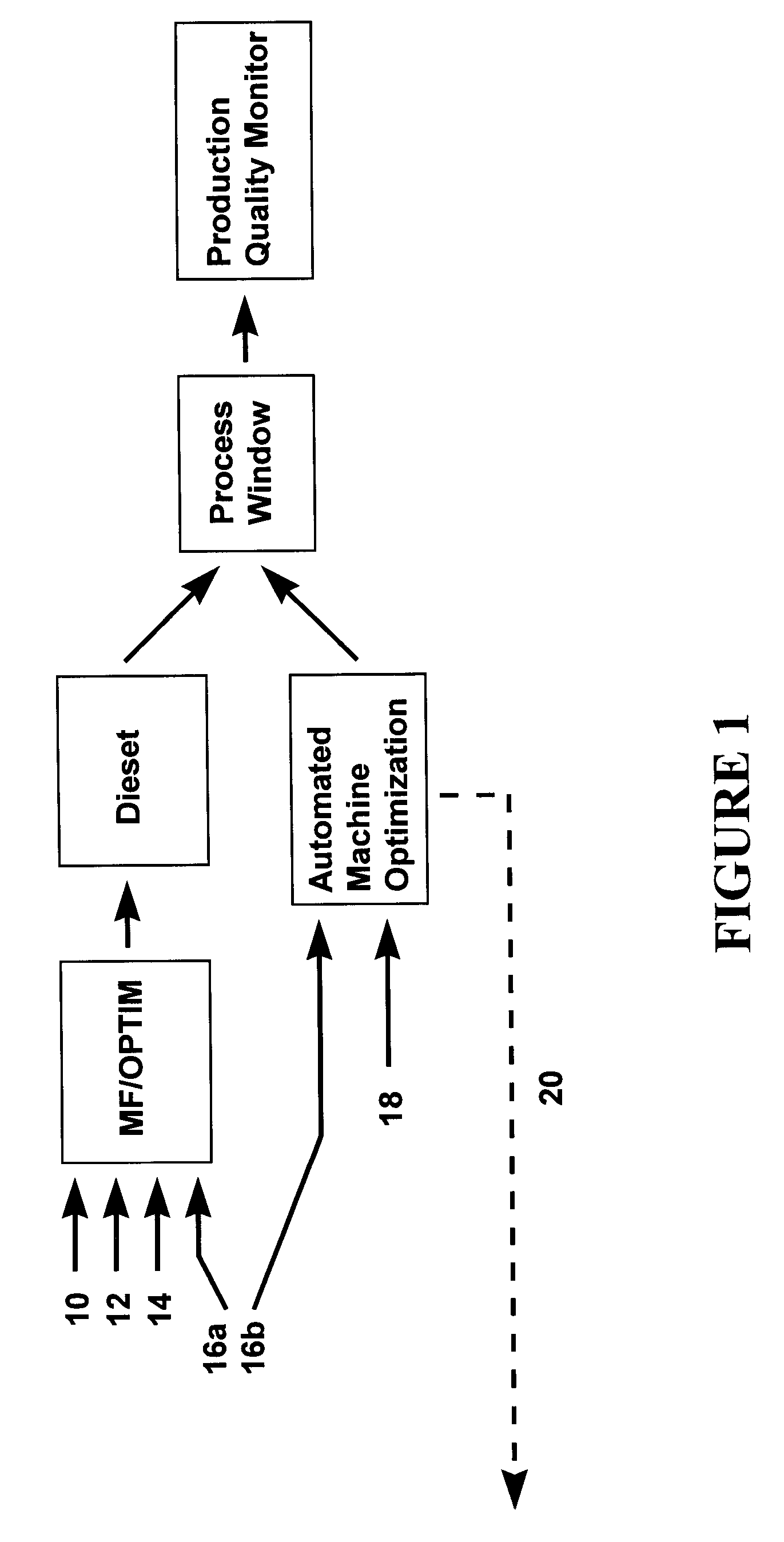
[0075] An Automated Molding Optimization (or AMO) method according to a preferred embodiment of the present invention is used in setting up the injection / filling velocity and packing / holding pressure profiles. Other injection molding machine parameters, including barrel temperatures, mold temperatures, cooling time and screw rotational velocity are presently the responsibility of the die setter.

[0076] The approach of AMO's velocity optimization is to profile regarding an inferred mold geometry, derived from the pressure differential. Pressure phase optimization is used to profile regarding an inferred polymer solidification, derived for a precise measurement of screw displacement. AMO determines machine and material characteristics in-line from the machine without the need for user interaction, resulting in optimized profiles that are ‘in-phase’ with the machine dynamics, material and mold geometry.

[0077]FIG. 1 is a flow chart summarizing the role of the AMO method according to a ...


PUM

PropertyMeasurementUnit
Fractionaaaaaaaaaa
Fractionaaaaaaaaaa
Fractionaaaaaaaaaa

Abstract

A method for the automated setting-up of an injection molding machine, the machine for manufacturing injection molded parts and including an injection screw and a configurable injection velocity, including the steps of: manufacturing one of more parts with the machine; determining an injection pressure profile by measuring injection pressure as a function of elapsed injection time with the machine configured with a substantially constant, desired injection velocity; measuring injection velocity as a function of elapsed injection time and determining a profile of the measured injection velocity; defining a mean pressure profile from the pressure profile in a regime of substantially constant measured injection velocity profile; adjusting the velocity profile over at least a portion of an injection velocity phase in response to the pressure profile to reduce differences between the pressure profile and the mean pressure profile, thereby tending to lessen irregularities in the pressure profile.

Description

RELATED APPLICATIONS [0001] This application is divided from application No. 09 / 601,955, which is the national stage of international application no. PCT / AU99 / 00067 claiming priority from Australian application no. PP1768 filed 12 Feb. 1998 whose content is incorporated herein by reference in its entirety.FIELD OF THE INVENTION [0002] The present invention relates to thermoplastic injection molding and in particular to the automation of the die setter's role in the setting of parameters of injection molding machines. The invention may also be applicable to reactive injection molding. BACKGROUND OF THE INVENTION [0003] Injection molding is one of the most important and efficient manufacturing techniques for polymeric materials, with the capability to mass produce high value added products, such as the compact disc. Injection molding can be used for molding other materials, such as thermoset plastics, ceramics and metal powders. The process in its present form was developed in the mid...

Claims


Application Information

Patent Timeline
IPC IPC(8): B29C45/76B29C47/96B29C45/77B29C48/96
CPCB29C45/766B29C45/7686B29C45/77B29C2043/5833B29C2945/76006B29C2945/76066B29C2945/7611B29C2945/76113B29C2945/76187B29C2945/76381B29C2945/76498B29C2945/76561B29C2945/76598B29C2945/76605B29C2945/76665B29C2945/76943
Inventor SPEIGHT, RUSSELL GORDON
Owner AUTODESK INC
Why Eureka
Try Eureka