Battery pack current monitoring

a current monitoring and battery pack technology, applied in secondary cell servicing/maintenance, cell components, instruments, etc., can solve the problems of overpower dissipation, additional components of current sense resistors, and connection costs

Inactive Publication Date: 2006-09-07
O2 MICRO INT LTD
View PDF22 Cites 14 Cited by
  • Summary
  • Abstract
  • Description
  • Claims
  • Application Information

AI Technical Summary

Benefits of technology

[0005] According to one aspect of the invention, there is provided a battery pack. The battery pack may include at least one battery cell, a switch having an ON resistance dependent on a temperature of the switch, a thermistor having a resistance varying with changes in the temperature, and battery state monitoring circuitry. The battery state monitoring circuitry may be configured to monitor a voltage drop across the switch caused by a current flowing through the switch and the resistance of the thermistor to correlate the voltage drop to the current.
[0006] According to another aspect of the invention, there is provided a cordless electrical device. The cordless electrical device may include a load and a battery pack to provide power to the load. The battery pack may include at least one battery

Problems solved by technology

However, for high current applications the current sense resistor may cause excessive power dissipat

Method used


Image

  • Battery pack current monitoring
  • Battery pack current monitoring
  • Battery pack current monitoring

Examples


Embodiment Construction

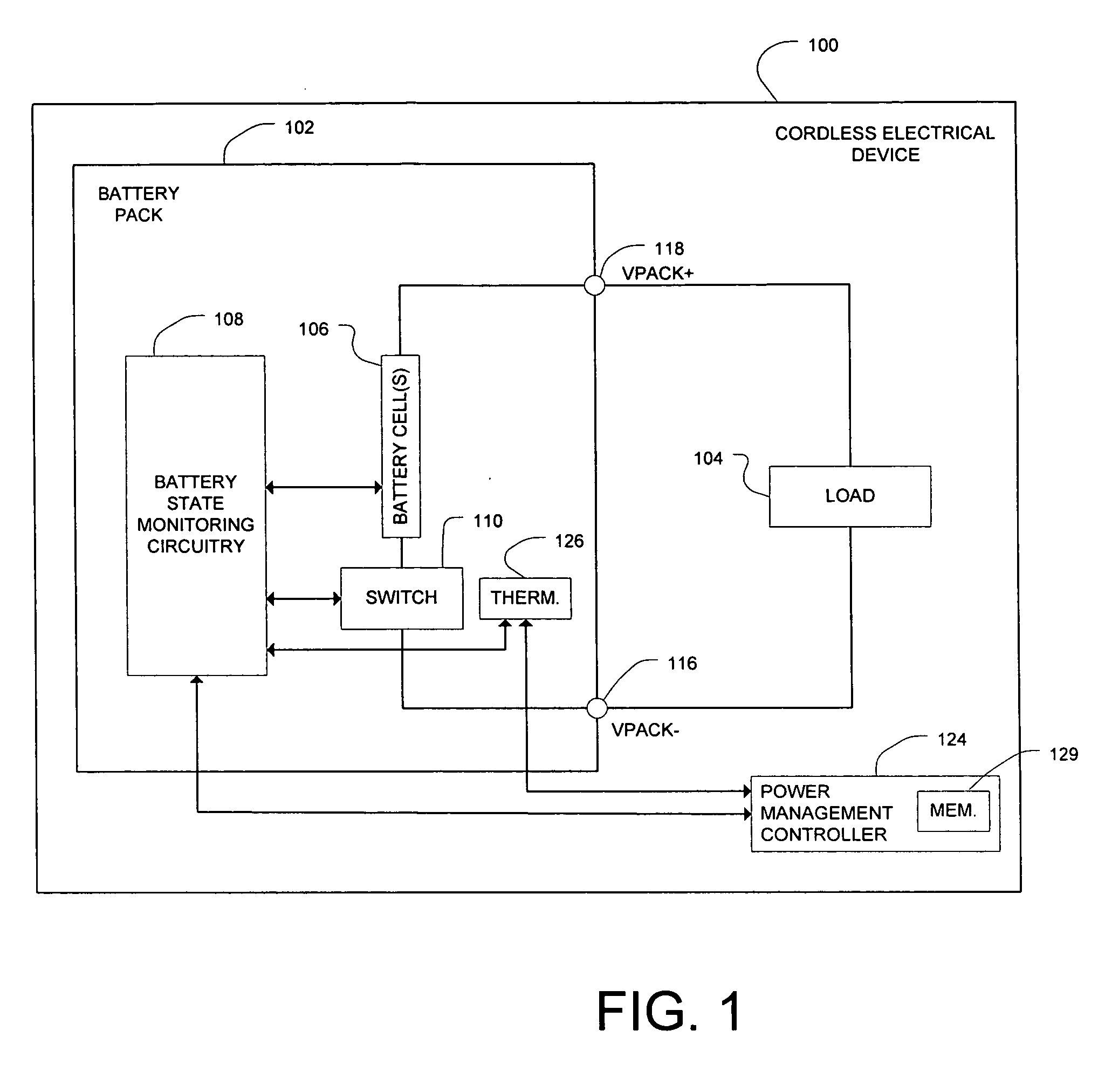
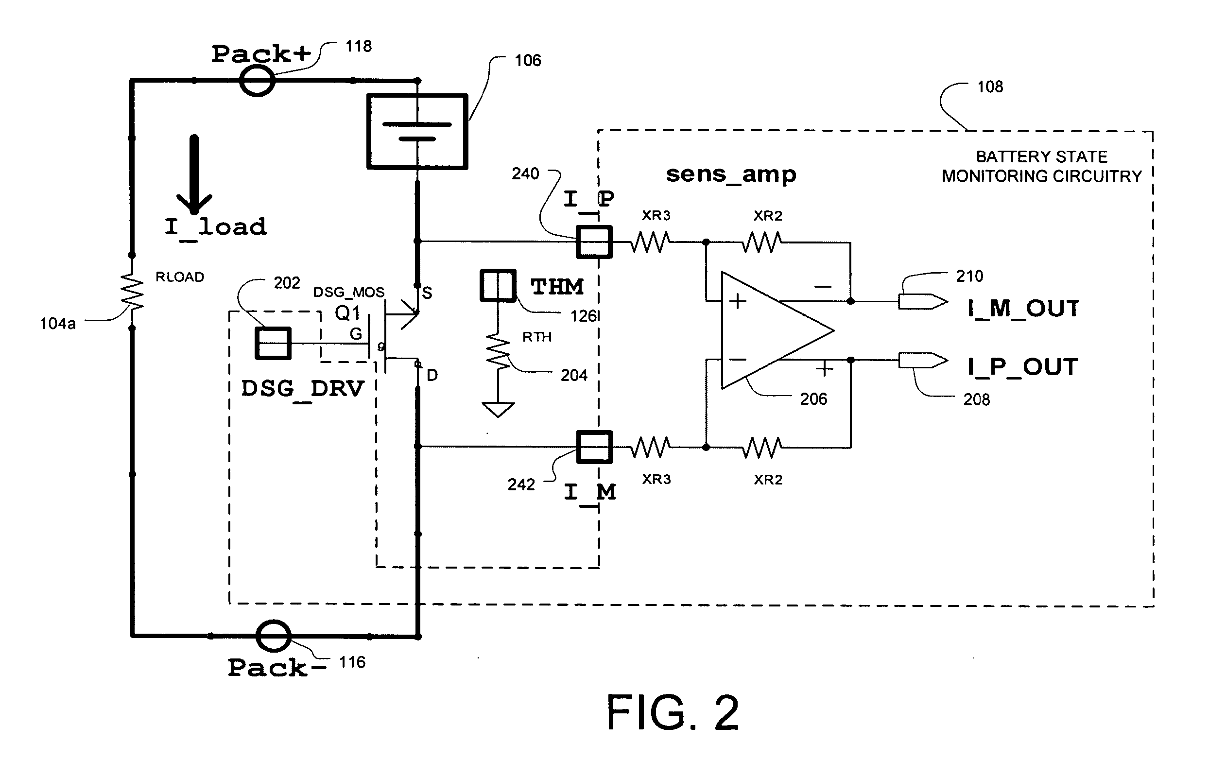
[0013]FIG. 1 illustrates a cordless electrical device 100 having a battery pack 102 that may provide power to the load 104 during a battery supply mode. The load 104 may represent the entire load of the device 100 that may be coupled to the VPACK+ terminal 118 and the VPACK− terminal 116 of the battery pack 102. The cordless electrical device 100 may include, but not be limited to, a laptop computer, a cell phone, a personal digital assistant, and a power tool such as a drill, a circular saw, a sander, etc. In one embodiment, the load 104 may be the power tool itself when the cordless electrical device is a power tool. In addition to providing power to the load 104 in the battery supply mode, the battery pack 102 may also be recharged by a DC power source (not illustrated) such as an ACDC adapter which may also simultaneously provide power to the load 104. In other instances, the battery pack 102 may be readily removed from the cordless electrical device 100 and coupled to an extern...


PUM


Abstract

A battery pack may include at least one battery cell, a switch having an ON resistance dependent on a temperature of the switch, a thermistor having a resistance varying with changes in the temperature, and battery state monitoring circuitry. The battery state monitoring circuitry may be configured to monitor a voltage drop across the switch caused by a current flowing through the switch and the resistance of the thermistor to correlate the voltage drop to the current level. A cordless electrical device including the battery pack, and an associated method are also provided.

Description

CROSS REFERENCE TO RELATED APPLICATIONS [0001] This application claims the benefit of the filing date of U.S. Provisional Application Ser. No. 60 / 659,330, filed Mar. 7, 2005, (Attorney Matter No. O2M05.03P), the teachings of which are incorporated herein by reference.FIELD [0002] The present disclosure relates to a battery pack for cordless electrical devices, and more particularly to battery pack current monitoring. BACKGROUND [0003] Various cordless electrical devices may be powered by a battery pack. Examples of such cordless electrical devices include, but are not limited to, laptop computers, cell phones, personal digital assistants, and power tools such as a drill. The battery pack may include a plurality of battery cells and power switches to allow the battery cells to either supply current (discharge operation mode) or to be charged (charge operation mode). The battery pack may also include battery state monitoring circuitry powered by the battery cells to perform of number ...

Claims


Application Information

Patent Timeline
IPC IPC(8): H02J7/00H01M50/202H01M50/204H01M50/269
CPCG01R19/16542H01M2/1016H01M10/4207H01M10/425H01M10/44H02J7/0031H02J7/0063Y02E60/10H02J7/007182H01M50/204H01M50/269H01M50/202
Inventor BUCUR, CONSTANTINNICULAE, MARIAN
Owner O2 MICRO INT LTD
Why Eureka
Try Eureka