Salient reflector for use on road

a technology for reflective reflectors and roads, applied in the direction of roads, instruments, construction, etc., can solve the problems of poor elasticity and breakdown of them, and achieve the effect of reducing the risk of damage, improving support, and avoiding over-deformation

Inactive Publication Date: 2006-09-07
LEE HUNGCHEN
View PDF2 Cites 1 Cited by
  • Summary
  • Abstract
  • Description
  • Claims
  • Application Information

AI Technical Summary

Benefits of technology

[0009] It is therefore a main object of the present invention to provide a salient reflector for use on road that can bring reflection effect designed in the original design into action fully, and efficiently prevent it from breaking down with high shock resistance.
[0011] Due to applying above-mentioned structure, the present invention adds a backup plate on the whole inner surface to prevent the filler from contacting with the prismatic specular surface, so efficiently bring the reflecting effect of original design into action fully; additionally, the counter prismatic surface formed on the top side of the backup plate exactly coordinating to the inner surface of the plate so that each coordinated prisms engage up together exactly to eliminate the gap between them further to improve the support, as laying on road, the salient plate is exerted with an extra force and deformed a bit due to the full area support coming from the backup plate to avoid over-deforming and damaging happened, the shock resistance of the plate is improved actually.

Problems solved by technology

Although adding a backup plate improves the performance, but above-mentioned salient reflector using on road still not gets to desired level of shock resistance, the sake is there is bigger gap exists between the plate 1 and the backup plate 4, and they are made of different materials—the plate 1 is made of PMMA (polymethyl methacrylate), and the backup plate 4 is made of plastic, and the elasticity of them is so poor that the plate 1 is easy to be broken down under over-tortuous when extra force exactly exerts on the non-rib spot.

Method used


Image

  • Salient reflector for use on road
  • Salient reflector for use on road
  • Salient reflector for use on road

Examples


Embodiment Construction

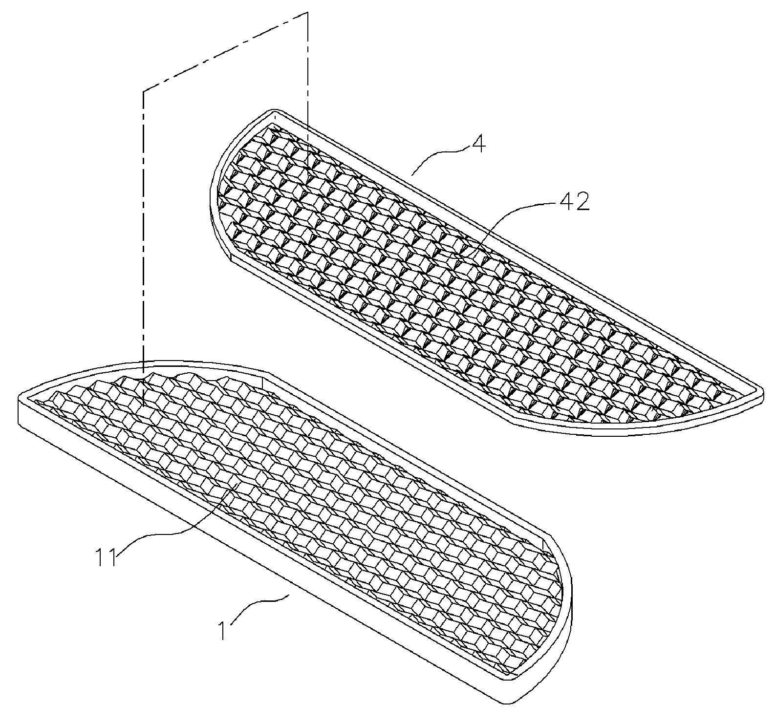
[0019] Referring to FIG. 6 to FIG. 7, a salient reflector for use on road provided of the present invention is typically consisted of a plate 1 with a prismatic specular surface 11 on full inner surface, and a backup plate 4 attaching on all the inner surface, wherein, coordinating to the inner prismatic specular surface 11 of the plate 1, a counter prismatic surface 42 is formed on the contacting surface of the backup plate 4 for matching said prismatic specular surface 11 exactly.

[0020] So, by means of the added backup plate 4, the present invention can efficiently prevent the filler 5 from contacting with the prismatic specular surface 11 directly, so as to bring the reflecting effect of the original design into action fully, and the gap between the plate 1 and the backup plate 4 is much smaller than the second to the fourth prior arts (as shown in FIG. 3 and FIG. 5), therefore, as the salient reflector laid on road is exerted under an extra force, the integrated plate 14 is jus...


PUM


Abstract

The present invention provides a salient reflector for use on road including a plate with a prismatic specular surface on full inner surface, and a backup plate attaching on all the inner surface, wherein, coordinating to the inner prismatic specular surface of the plate, a counter prismatic surface is formed on the contacting surface of the backup plate for matching said prismatic specular surface exactly. The present invention can bring the reflecting effect of the original design into action fully, and avoids breaking down, and really improves the shock resistance of the goods.

Description

BACKGROUND OF THE INVENTION [0001] 1. Field of the Invention [0002] The present invention relates to a salient reflector for use on road, and more particularly to a salient reflector laid on road with high shock resistance and crush resistance. [0003] 2. Description of Prior Art [0004] In accordance with a conventional salient reflector for use on road, as shown in FIG. 1, it is just only a plate 1 with prismatic specular surface 11 at inside surface, and there is not any rib reinforcement on it. As laying on road, the inside surface of the plate 1 is processed in electroplating treatment so as to attach a safety film 2 (as shown in FIG. 2) on the prismatic specular surface 11 firstly, then stuff some filler 5 (epoxy resin and silica sand composition) at inside so that it can be fastened on road as a salient reflector. [0005] Due to no any rib reinforcement formed on the plate 1 of the conventional salient reflector, as it is fastened saliently on road, bearing on rolling of vehicle...

Claims


Application Information

Patent Timeline
Patent Type & Authority Applications(United States)
IPC IPC(8): G02B5/12
CPCE01F9/06E01F9/553
Inventor LEE, HUNGCHEN
Owner LEE HUNGCHEN
Why Eureka
Try Eureka