Supercharge Your Innovation With Domain-Expert AI Agents!

Self leveling bracket/stabilizer for fluorescent lighting fixtures with controlled uplight capability

a technology of fluorescent lighting fixtures and self-leveling brackets, which is applied in the direction of fixed installation, lighting and heating apparatus, light source combinations, etc., can solve the problems of increasing eyestrain, wasting light usage, and too much uplighting, so as to eliminate several costly components

Inactive Publication Date: 2006-09-07
PHILIPS ELECTRONICS NORTH AMERICA
View PDF8 Cites 6 Cited by
  • Summary
  • Abstract
  • Description
  • Claims
  • Application Information

AI Technical Summary

Benefits of technology

"The invention is a fixture for lighting that can accommodate different lengths and designs of fluorescent tubes. It has a central section with a full upper housing that protects the lamps from dust and debris while providing controlled lighting. The fixture has wing sections that extend out from the central section at an angle, allowing for uplighting in a controlled fashion. The fixture can be attached to a pendant bracket or a quick bracket for easy installation. The fixture is designed to suspend level to the floor and can be used with existing threaded rods or hooks. It is an economical and efficient solution for lighting buildings."

Problems solved by technology

The cave effect causes a glare-filled, enclosed effect, which increases eyestrain.
However, too much uplighting is inefficient and wasteful, not reflecting a large portion of emitted light back to the space below the fixture.
To provide uptight, it is known to have an open top, which wastes light usage, as much of the light is not reflected back to the space below the fixture.
In addition, in general, however, lamp fixtures with open tops have a susceptibility to dirt accumulation.
Furthermore, if one would make a fixture similar to that of Ohm '377 with a non-translucent wall, the fixture efficiency would be greatly diminished.
In addition, the lack of a photometrically designed reflector would diminish the obtainable efficiency of the fixture.
Their rounded lenses are not as efficient as using a flat lens.
These upper lamps are exposed and subject to dirt accumulation.
U.S. Pat. No. 2,320,829 of Naysmith and U.S. Pat. No. 2,323,002 of Baker both describe V-shaped arrangement of lamps, which does not control uptight.

Method used


Image

  • Self leveling bracket/stabilizer for fluorescent lighting fixtures with controlled uplight capability
  • Self leveling bracket/stabilizer for fluorescent lighting fixtures with controlled uplight capability
  • Self leveling bracket/stabilizer for fluorescent lighting fixtures with controlled uplight capability

Examples


first embodiment

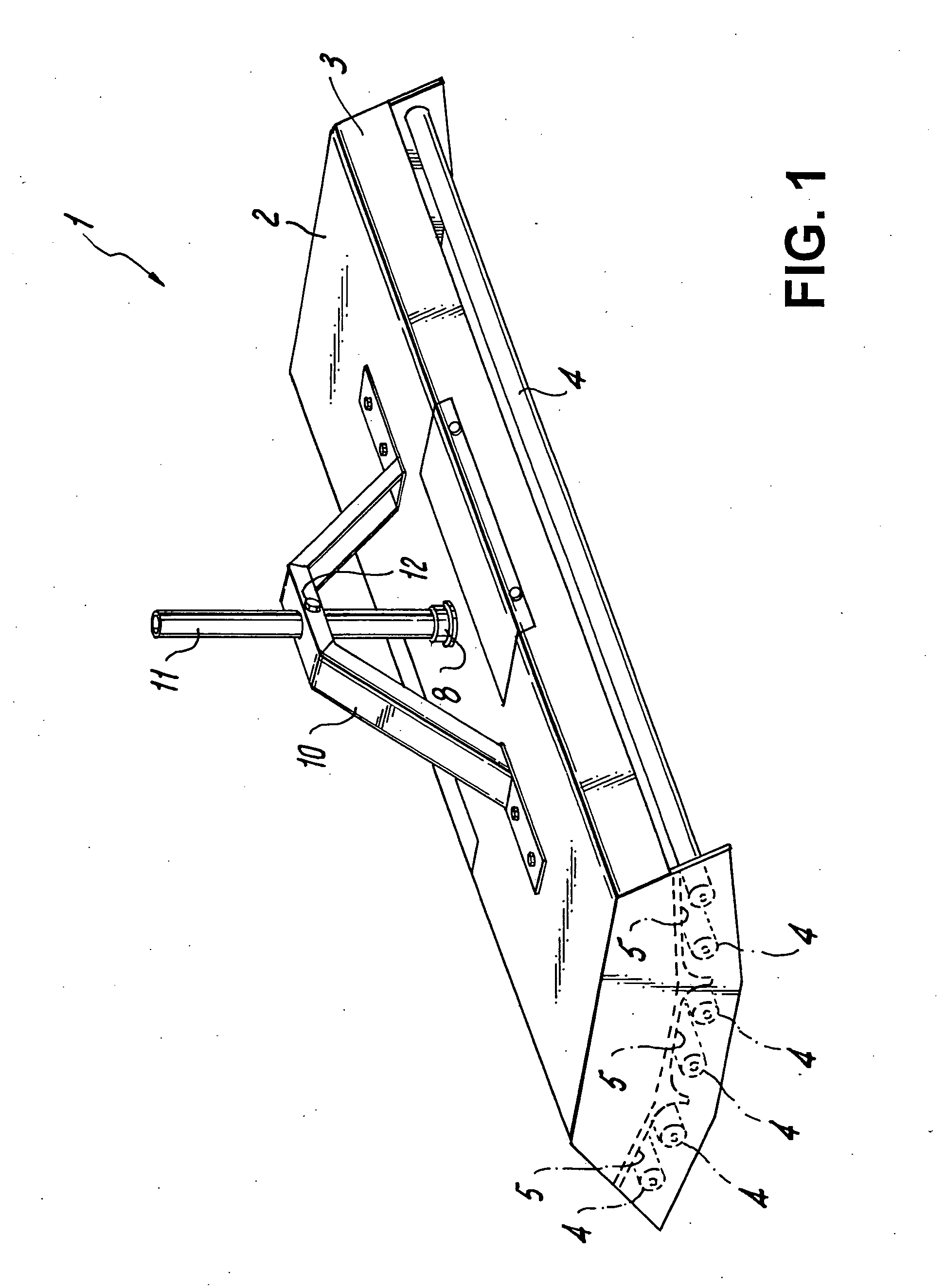
[0049]FIG. 1 shows this invention, wherein fixture 1 uses no lenses. Fixture 1 has six straight fluorescent tubes 4 within housing 2 with shortened oblique walls 3. Central concave reflector 6 is aimed straight down while side reflectors 5 are angled obliquely and have no curved section (or a very truncated one) at their distal ends. Reflector surface finish can vary, however a white finish, a specular reflector, or an enhanced specular reflector surface with 95% reflectivity are currently offered.

[0050] Pendant pipe 11 is used to attach fixture 1 to a ceiling structure; it also carries wiring within. It is mounted in hub 8 and is located accurately by trapezoidal pendant bracket 10 and secured by pendant screw 12. However, pendant bracket 10 is usable on any type of suspended light fixture, to stabilize the fixture in place.

second embodiment

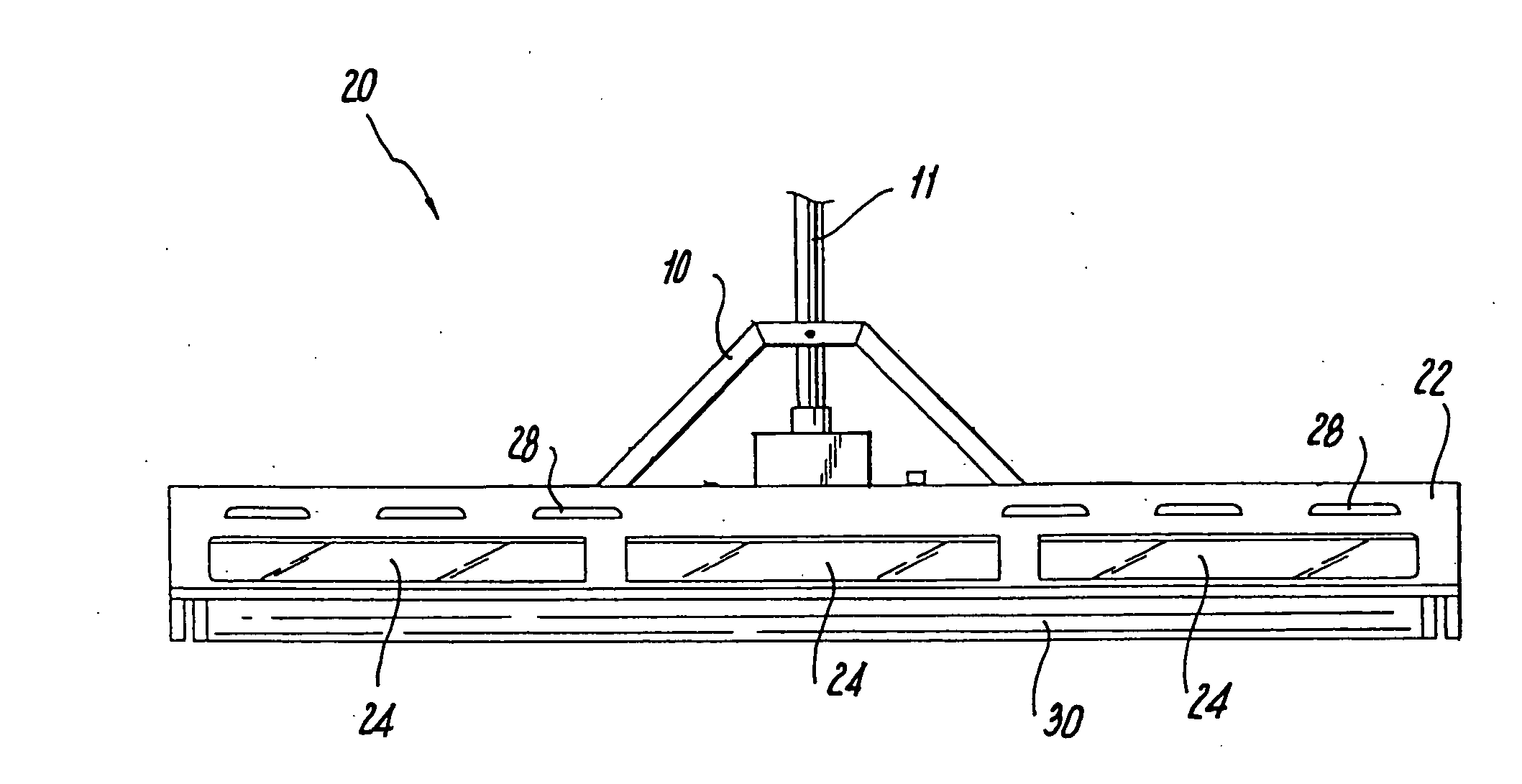
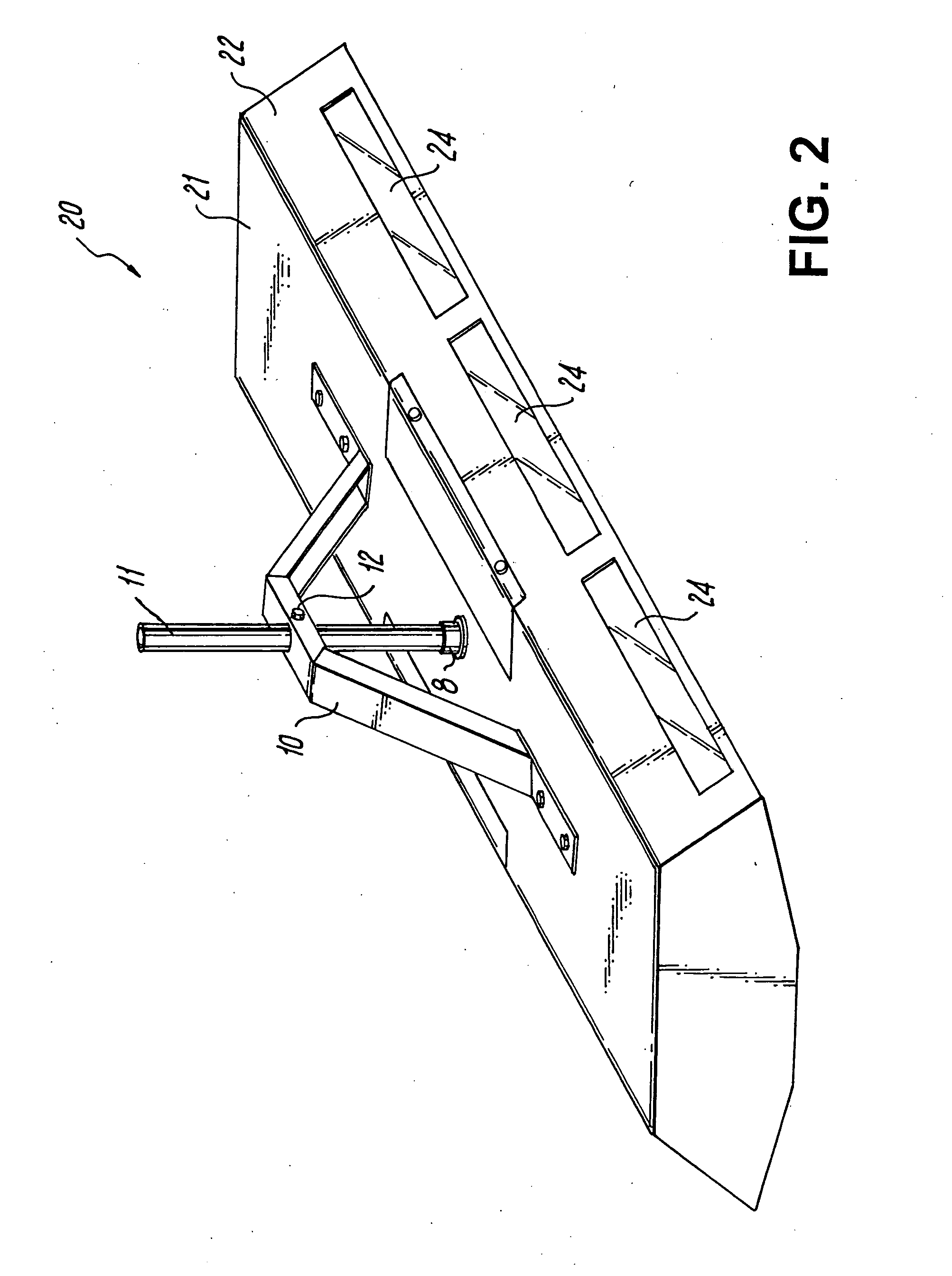
[0051] In a second embodiment, fixture 20 of FIG. 2 has housing 21 with full oblique walls 22. Walls 22 have three rectangular windows 24 with flat high efficiency lenses to permit a controlled amount of uplighting.

[0052]FIGS. 3, 4, and 5 present top, side and end views of fixture 20 respectively. Vent louvers 28 are used to permit air circulation for cooling of ballasts and lamps while excluding dust contamination. High efficiency downlight lens 30 covers the fluorescent tubes.

[0053] A variety of lamp configurations for the fixtures of this invention are shown in the end views of FIGS. 6-10.

[0054] For example, FIG. 6 shows a 3-lamp fixture 40 with a single lamp 4 in central reflector 41 and a single lamp in each side reflector 42.

[0055]FIG. 7 shows a 4-lamp fixture 50 with two lamps within central reflector 51 and single lamps within side reflectors 52.

[0056]FIG. 8 shows a 5-lamp configuration 60 with a single lamp in central reflector 61 and two lamps in each side reflector 62...


PUM

PropertyMeasurementUnit
transparentaaaaaaaaaa
sizesaaaaaaaaaa
lengthsaaaaaaaaaa

Abstract

A fluorescent light fixture is suspended by a longitudinally extending trapezoidal pendant bracket / stabilizer. The trapezoidal pendant bracket / stabilizer includes a horizontally extending top brace and a pair of obliquely extending arms extending downward in opposite directions from the top brace in a trapezoidal crossection. Each obliquely extending arm has a flat, horizontally and outwardly extending attachment foot extending longitudinally along a flat top surface of the fluorescent lamp fixture, wherein each attachment foot is attached to the flat top surface of the fluorescent lamp fixture. The horizontally extending top brace is attachable to a ceiling mounted fastener, such as a toggle hanger or other downwardly extending fastener.

Description

RELATED APPLICATIONS [0001] This application is a continuation-in-part of application Ser. No. 10 / 750,391, filed Dec. 31, 2003, and claims priority under 35 U.S.C. §120 in part therefrom.FIELD OF THE INVENTION [0002] The present invention relates indoor lighting with controlled uptight capability. BACKGROUND OF THE INVENTION [0003] In order to make a large area visually comfortable, downlight fixtures often include some uptight capabilities, to reduce the “cave” effect caused by ceiling fixtures being too intense for the viewer to see the ceiling beyond the fixtures. The cave effect causes a glare-filled, enclosed effect, which increases eyestrain. [0004] However, too much uplighting is inefficient and wasteful, not reflecting a large portion of emitted light back to the space below the fixture. [0005] To provide uptight, it is known to have an open top, which wastes light usage, as much of the light is not reflected back to the space below the fixture. In addition, in general, howe...

Claims


Application Information

Patent Timeline
Patent Type & Authority Applications(United States)
IPC IPC(8): F21S4/00F21S8/06F21V5/02F21V7/00F21V15/01F21V29/00
CPCF21V5/02F21V7/0016F21V7/005Y10T29/49947F21V29/004F21Y2103/00F21S8/063F21V15/01F21Y2113/00F21V29/83
Inventor KASSAY, CHARLES E.KASSAY, SUZANNE M.KASSAY, MARC A.KASSAY, JOHN P.
Owner PHILIPS ELECTRONICS NORTH AMERICA
Features
  • R&D
  • Intellectual Property
  • Life Sciences
  • Materials
  • Tech Scout
  • Unparalleled Data Quality
  • Higher Quality Content
  • 60% Fewer Hallucinations
Learn More