Technique for selecting a path computation element based on response time delay

a path computation and response time delay technology, applied in the field of computer networks, can solve the problems of path computation at the head-end lsr, and the pcc does not have sufficient information to adequately select a pce based on its actual available path computation resources, so as to reduce the set-up time, efficient select an appropriate, and accelerate convergence

Active Publication Date: 2006-09-07
CISCO TECH INC
View PDF12 Cites 56 Cited by
  • Summary
  • Abstract
  • Description
  • Claims
  • Application Information

AI Technical Summary

Benefits of technology

[0024] Advantageously, the novel technique efficiently selects an appropriate PCE to compute a path, such as a Traffic Engineering (TE) label switched path (LSP), between nodes of a network to thereby reduce a set-up time for the TE-LSP and allows for faster convergence. TE-LSP set-up times are gen...

Problems solved by technology

Since management of a large system of interconnected computer networks can prove burdensome, smaller groups of computer networks may be maintained as routing domains or autonomous systems.
One difficulty that arises in crossing AS boundaries is that path computation at the head-end LSR requires knowledge of network topology and resources across the entire network between the head-end...

Method used


Image

  • Technique for selecting a path computation element based on response time delay
  • Technique for selecting a path computation element based on response time delay
  • Technique for selecting a path computation element based on response time delay

Examples


Embodiment Construction

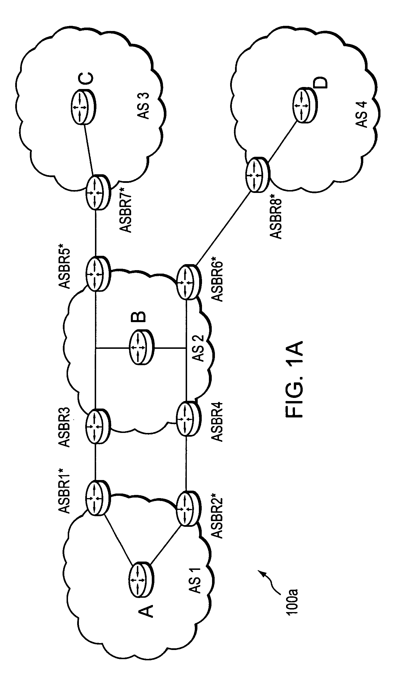
[0036]FIG. 1A is a schematic block diagram of an exemplary computer network 100a comprising autonomous system AS2, which is interconnected with a plurality of other autonomous systems AS1, AS3, and AS4. An Autonomous System (AS) is herein defined to be a group of intermediate nodes, such as intradomain routers, within a network that are subject to a common authority and execute one or more intradomain routing protocols. Although, each AS is illustratively an autonomous system, those skilled in the art will appreciate that the ASes may alternatively be configured as routing domains or other networks or subnetworks. The autonomous system AS1 includes intradomain routers such as border routers ASBR1* and ASBR2* through which communication, such as data packets, may pass into and out of the autonomous system to border routers ASBR3 and ASBR4, respectively of AS2. AS2 also includes border routers ASBR5* and ASBR6* in communication with border routers ASBR7* and ASBR8* of ASes 3 and 4, re...


PUM


Abstract

A technique efficiently selects a path computation element (PCE) to compute a path between nodes of a computer network. The PCE selection technique is illustratively based on dynamic advertisements of the PCE's available path computation resources, namely a predictive response time (PRT). To that end, the novel technique enables one or more PCEs to dynamically send (advertise) their available path computation resources to one or more path computation clients (PCCs). In addition, the technique enables the PCC to efficiently select a PCE (or set of PCEs) to service a path computation request based upon those available resources.

Description

RELATED APPLICATIONS [0001] This application claims the benefit of U.S. Provisional Application Ser. No. 60 / 658,003, entitled TECHNIQUE FOR SELECTING A PATH COMPUTATION ELEMENT BASED ON RESPONSE TIME DELAY, filed by Vasseur et al. on Mar. 2, 2005, the contents of which are hereby incorporated in their entirety. [0002] This application is also related to U.S. patent application Ser. No. 10 / 983,280, entitled TECHNIQUE FOR SELECTING A PATH COMPUTATION ELEMENT, filed by Vasseur et al. on Nov. 5, 2004, the contents of which are hereby incorporated in its entirety.BACKGROUND OF THE INVENTION [0003] 1. Field of the Invention [0004] The present invention relates to computer networks and more particularly to selecting path computation elements for computing paths through a computer network. [0005] 2. Background Information [0006] A computer network is a geographically distributed collection of nodes interconnected by communication links and segments for transporting data between end nodes, s...

Claims


Application Information

Patent Timeline
IPC IPC(8): G01R31/08H04L12/56H04L12/28H04L12/26G06F11/00H04J3/14H04J1/16H04L1/00H04J3/22H04J3/16G08C15/00
CPCH04L12/4633H04L67/16H04L47/10H04L67/1068H04L67/104H04L67/51H04L45/12H04L47/12H04L69/16
Inventor VASSEUR, JEAN-PHILIPPEORAN, DAVID R.
Owner CISCO TECH INC
Why Eureka
Try Eureka