Probe structure for an ear thermometer

Inactive Publication Date: 2006-09-07
CHEN KUN SUNG +5
View PDF5 Cites 10 Cited by
  • Summary
  • Abstract
  • Description
  • Claims
  • Application Information

AI Technical Summary

Benefits of technology

[0018] An objective of the present invention is to provide a probe structure for an ear thermometer. In particular, the present invention improves the design of the probe. In the present invention, the sensor unit is mov

Problems solved by technology

Nowadays, people are not satisfied with conventional contact-type thermometers, such as mercury thermometers or electronic thermometers.
However, if a temperature difference occurs between the waveguide 106 and the infrared sensor 104, the temperature measured by the thermometer will be erroneous.
However, if the waveguide 106 transmits heat to the infrared sensor 104, it will

Method used


Image

  • Probe structure for an ear thermometer
  • Probe structure for an ear thermometer
  • Probe structure for an ear thermometer

Examples


Example

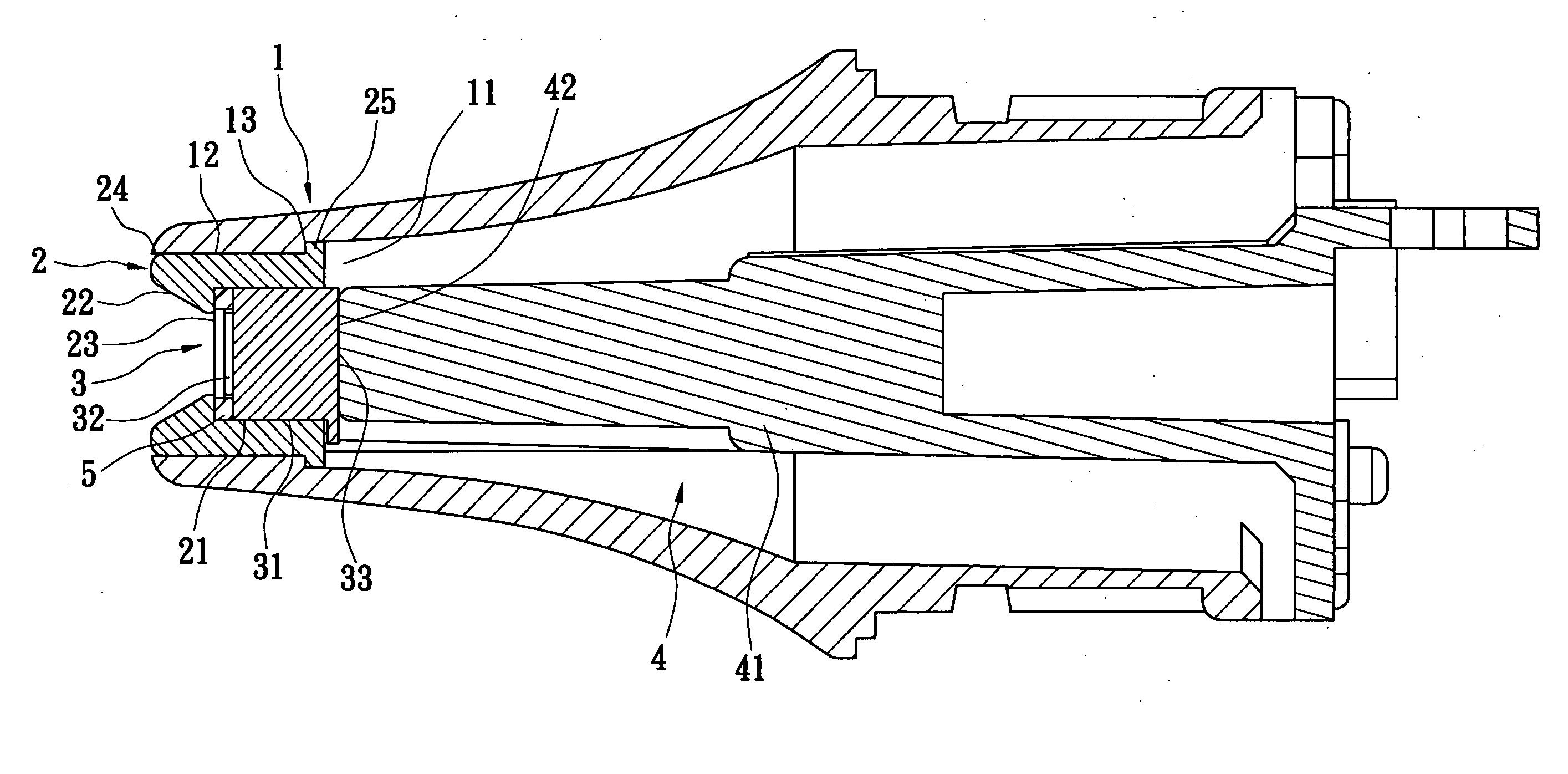
[0027] Reference is made to FIG. 4, which is a cross-sectional view of a probe of an ear thermometer in accordance with the present invention. It includes a housing 1, a sleeve component 2, a sensor unit 3 and a holding component 4.

[0028] The shape of the housing 1 is suitable to be placed inside a human's external ear canal so that the housing 1 can be inserted into the external ear canal during temperature measurement. The housing 1 is formed with a first containing room 11 inside and an opening at its front end, in which the opening is connected with the first containing room 11. The housing 1 has a connecting portion 13 formed between its inner wall 12 and the first containing room 11.

[0029] The sleeve component 2 is a hollow cylinder and combined with the housing 1 via an ultrasonic meld. In practice, the sleeve component 2 can also be combined with the housing via mold injection to form a partial structure for the housing 1. The sleeve component 2 is disposed in the first co...


PUM


Abstract

A probe structure for an ear thermometer includes a housing, a sleeve component, a sensor unit and a holding component. The housing has a first containing room to contain the sleeve component having a second containing room. The sleeve component has a front end formed with a reflective surface. The sensor unit is placed inside the second containing room and has a window, via which the sensor unit detects heat radiation. The sleeve component is used to lower heat radiation impact upon the sensor unit and prevent inexact measurements by the sensor unit caused by detecting objects other than the measured object. The sleeve component helps to reflect heat radiation from the measured object to the infrared sensor. This sensor unit functions well even though it is not disposed at the front most end of the probe. The holding component has one end against the bottom of the sensor unit.

Description

BACKGROUND OF THE INVENTION [0001] 1. Field of the Invention The present invention is related to a probe structure for an ear thermometer and, more particularly, to a probe for an infrared thermometer for measuring the temperature of a human ear. [0002] 2. Description of Related Art [0003] Nowadays, people are not satisfied with conventional contact-type thermometers, such as mercury thermometers or electronic thermometers. They desire exacter, speedier, easy to measure, easy to read, harmless and non-invasive temperature-measuring devices or methods. At present, non-contact infrared thermometers meet the foresaid requirements. Hence, people are willing to pay more for and are more interested in this kind of thermometer, so various kinds of infrared thermometers have been developed over time. [0004] In general, an infrared thermometer has a probe projected therefrom. One can place the probe in an external ear canal to measure a person's temperature. The probe has an infrared sensor ...

Claims


Application Information

Patent Timeline
IPC IPC(8): G01K1/00G01J5/00
CPCG01J5/04G01J5/049G01J5/06G01K1/20
Inventor CHEN, KUN-SUNGLIN, YING-CHAOOUYANG, HSINGOUYANG, YAOHUANG, KUO-HUNGLIN, CHIU-JUNG
Owner CHEN KUN SUNG
Why Eureka
Try Eureka