
Wireless data communication system and wireless data communication method

a wireless data communication and wireless data technology, applied in the field of wireless data communication system and wireless data communication method, can solve the problems of deteriorating transmission characteristics and less effective enhancement of transmission rate, and achieve the effect of reducing the iq mismatch generated in mimo communication

Inactive Publication Date: 2006-09-07
HITACHI LTD
View PDF8 Cites 51 Cited by
  • Summary
  • Abstract
  • Description
  • Claims
  • Application Information

AI Technical Summary

Benefits of technology

The patent describes a method for improving the transmission of signals in a MIMO system, which uses multiple antennas at both the transmitting and receiving ends. The method involves a training process to obtain the transfer matrix between the transmitting and receiving antennas. The training process involves transmitting a known signal and analyzing the received signal to determine the transfer matrix. The transfer matrix is then used to restore the transmitted signal from the received signal. The patent also discusses the impact of IQ mismatch on the transmission characteristics and proposes methods to address this issue. The technical effect of the patent is to improve the transmission quality and stability of the MIMO system.

Problems solved by technology

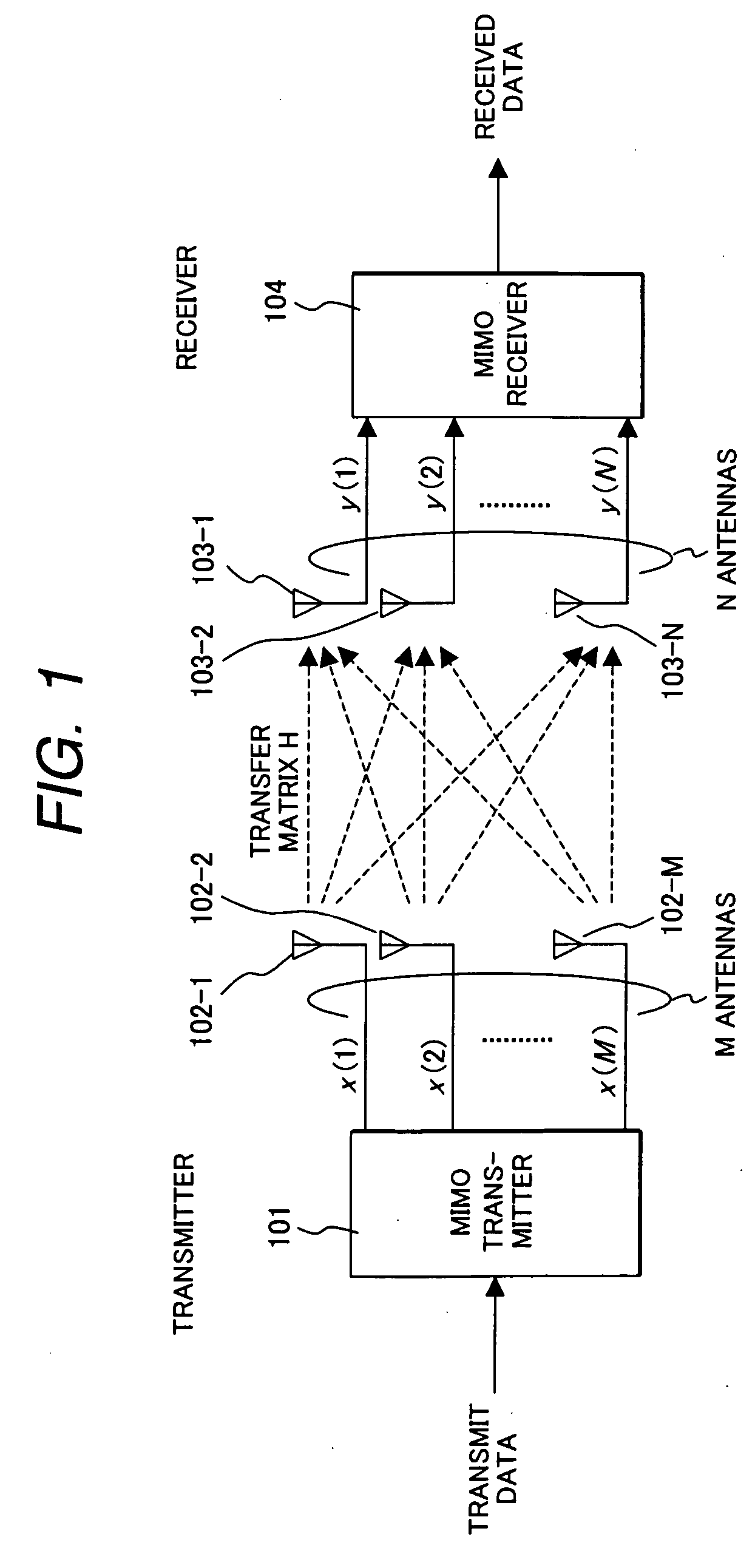
The beam forming or the diversity technology can reduce deterioration in transmission characteristics caused by noise or interference in order to improve reception sensitivity; however, they are less effective in enhancing a transmission rate.
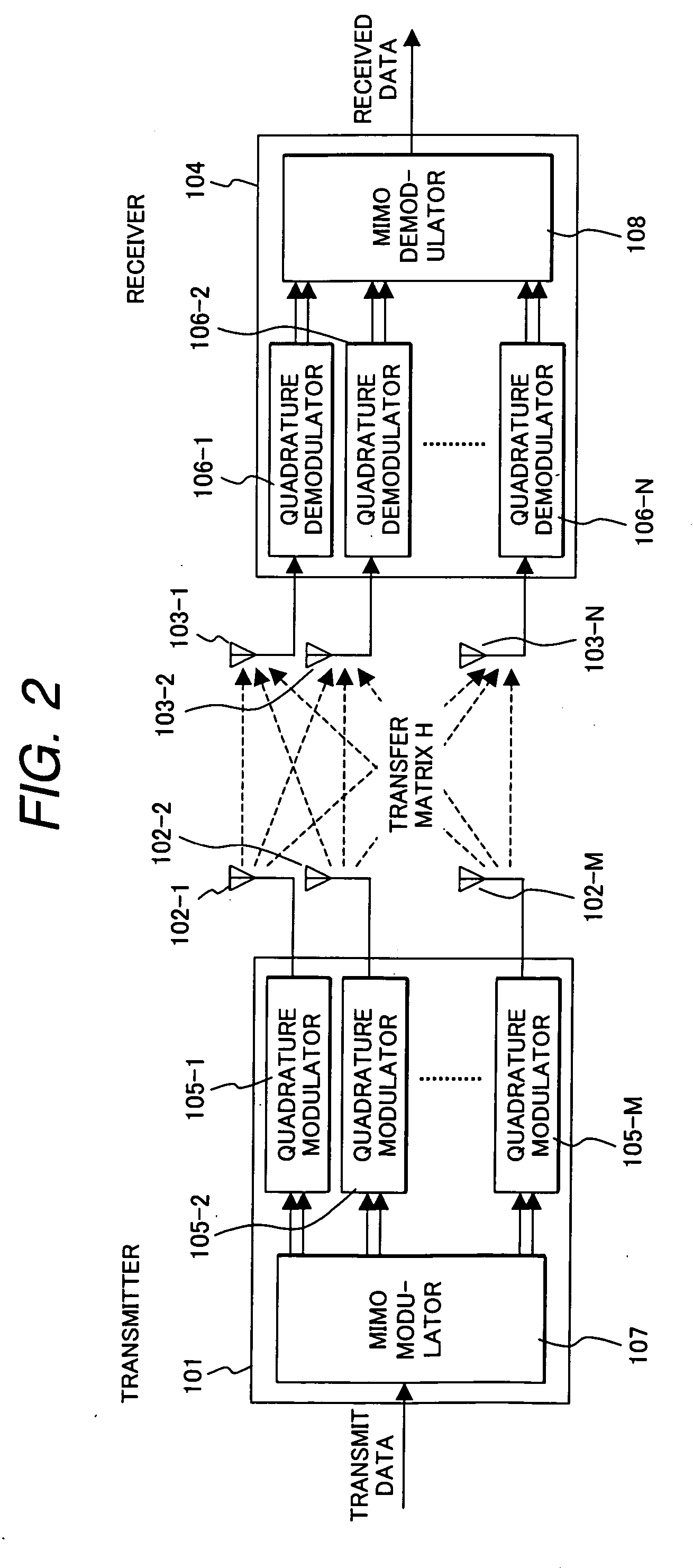
However, in building a MIMO transmission system, there is a problem in that IQ mismatch in a quadrature modulator and a quadrature demodulator causes significant impact, thus deteriorating transmission characteristics, as shown in the following non-patent references 1 and 2.

Method used


Image

  • Wireless data communication system and wireless data communication method
  • Wireless data communication system and wireless data communication method
  • Wireless data communication system and wireless data communication method

Examples


first embodiment

[0046] Hereinafter, a first preferred embodiment according to the present invention will be described with reference to FIG. 4 to 7.

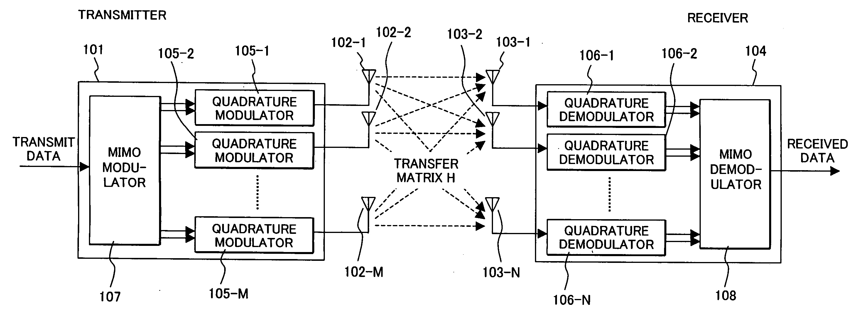
[0047]FIG. 4 is a diagram illustrating a configuration of a data communication system and a matrix representing a transfer matrix according to the first embodiment of the present invention. FIG. 5 is a diagram illustrating only a receiver shown in FIG. 4. FIG. 6 is a diagram illustrating only a transmitter shown in FIG. 4.

[0048]FIG. 7 is a graph comparatively showing SNR vs. BER characteristics of communication methods according to the prior art and the present invention.

[0049] In a MIMO transmitter 101 of an MIMO wireless data communication system according to the present invention, first, after processes such as serial-parallel conversion, error correction coding and interleaving in an MIMO modulator 107 is carried out, a signal is then converted to a complex number expression. Here, a MIMO encoding is carried out and complex signals as many as the...

second embodiment

[0065] Next, a method for giving a training signal in the MIMO data communication of the present invention will be described with reference to FIGS. 8 to 11.

[0066]FIG. 8 is a diagram illustrating a constellation example of a training signal having two linearly-independent signal points. FIG. 9 is a diagram illustrating a constellation example of a training signal on a QPSK modulation signal. FIGS. 10 and 11 are diagrams illustrating configuration relationship between a training signal and data and a method for giving a constellation on a BPSK (Binary Phase Shift Keying) modulation signal.

[0067] According to the method of the present invention, since a transfer matrix in MIMO transfer is represented by dividing the matrix into an in-phase component and a quadrature component of a complex signal, it is necessary to set two or more signal points that are linearly independent on the constellation of a training signal of the transfer matrix. For example, since signal points 109-1 and 1...


PUM


Abstract

In MIMO transmission which executes quadrature modulation of M transmission antennas and N reception antennas, a transmission signal vector will be set as a vector having the element number of 2M that comprises the in-phase components and quadrature components of M complex signals, a reception signal vector will be set as a vector having the element number of 2N that comprises the in-phase components and quadrature components of N complex signals, and a transfer matrix will be set as a real matrix comprising 2N rows and 2M columns. Then, a transfer matrix containing IQ mismatch is obtained based on a training signal, thereby executing MIMO encoding and decoding. For learning of the transfer matrix, a training signal which has two linearly-independent signal points on a constellation for each of the transmission antennas is used. With such arrangement, it is possible, in MIMO wireless data transmission, to compensate deterioration in a bit error rate that is caused by IQ mismatch in a quadrature modulator and a quadrature demodulator.

Description

CLAIM OF PRIORITY [0001] The present application claims priority from Japanese application JP 2005-057206, filed on Mar. 2, 2005, the content of which is hereby incorporated by reference into this application. FIELD OF THE INVENTION [0002] The present invention relates to a wireless data communication system and a wireless data communication method, and more specifically to a wireless data communication system and a method for wireless data communication which is suitably used for MIMO (Multiple-Input Multiple-Output) communication, which receives wireless data from a plurality of transmission antennas by using a plurality of reception antennas. BACKGROUND OF THE INVENTION [0003] With conventional wireless communication systems, to improve reception sensitivity, a technology to transmit a signal from a transmitter by using a plurality of antennas and a technology to receive a signal by using a plurality of antennas are employed. These technologies are called “beam forming” or “diver...

Claims


Application Information

Patent Timeline
Patent Type & Authority Applications(United States)
IPC IPC(8): H04L1/02H04J99/00
CPCH04B7/0413H04B7/0619H04B7/0678H04L25/0226H04L27/364H04L27/3863
Inventor HAYASE, SHIGENORI
Owner HITACHI LTD
Learn More