Image forming apparatus and control method for the same

a technology of image forming apparatus and control method, which is applied in the direction of electrographic process apparatus, instruments, optics, etc., can solve the problems of omitting operation, user is required to perform complicated operations, and the influence of the fixing process cannot be reflected on the toner density control, so as to improve color stability, high accuracy of read timing of patch image, and high accuracy of density adjustmen

Active Publication Date: 2006-09-07
CANON KK
View PDF5 Cites 16 Cited by
  • Summary
  • Abstract
  • Description
  • Claims
  • Application Information

AI Technical Summary

Benefits of technology

[0023] It is an object of the present invention is to provide an image forming apparatus and a control method therefor that are capable of

Problems solved by technology

Therefore, when the toner density control is executed based on the toner density information, influences after the fixing process cannot be reflected on the toner density control.
With this method, however, a user is required to perform complicated operation such as picking up an output sheet, on which an image is formed by the printer unit, from a sheet discharge section, feeding the output sheet in the reader unit, and setting the reader unit to be ready for image reading.
Because of the complexity of operation, some users omit the operation which should be done periodically.
On the other hand, the ink jet printer has a problem that colors of inks printed on a sheet vary, though not so much as in the electronic photographic printer, due to variation in the amount of discharged ink with passage of time, differences in environment, or individual differences between ink cartridges.
As described above, in the direct imaging printer, the most important problem is to maintain color stability irrespective of whether the printer is based on the electronic photographic technique or the ink jet technique.
However, the arrangement for executing the color stabilizing control of an output image using a sensor set, as in the above-mentioned prior art example, on a conveying path on the side downstream of the fixed device entails the following problems.
If, on the other hand, a toner patch image is detected after it has been fixed on a sheet by, for example, detecting the toner patch image when a predetermined time has elapsed from the completion of the toner patch image being fixed, erroneous detection may sometimes b

Method used


Image

  • Image forming apparatus and control method for the same
  • Image forming apparatus and control method for the same
  • Image forming apparatus and control method for the same

Examples


first embodiment

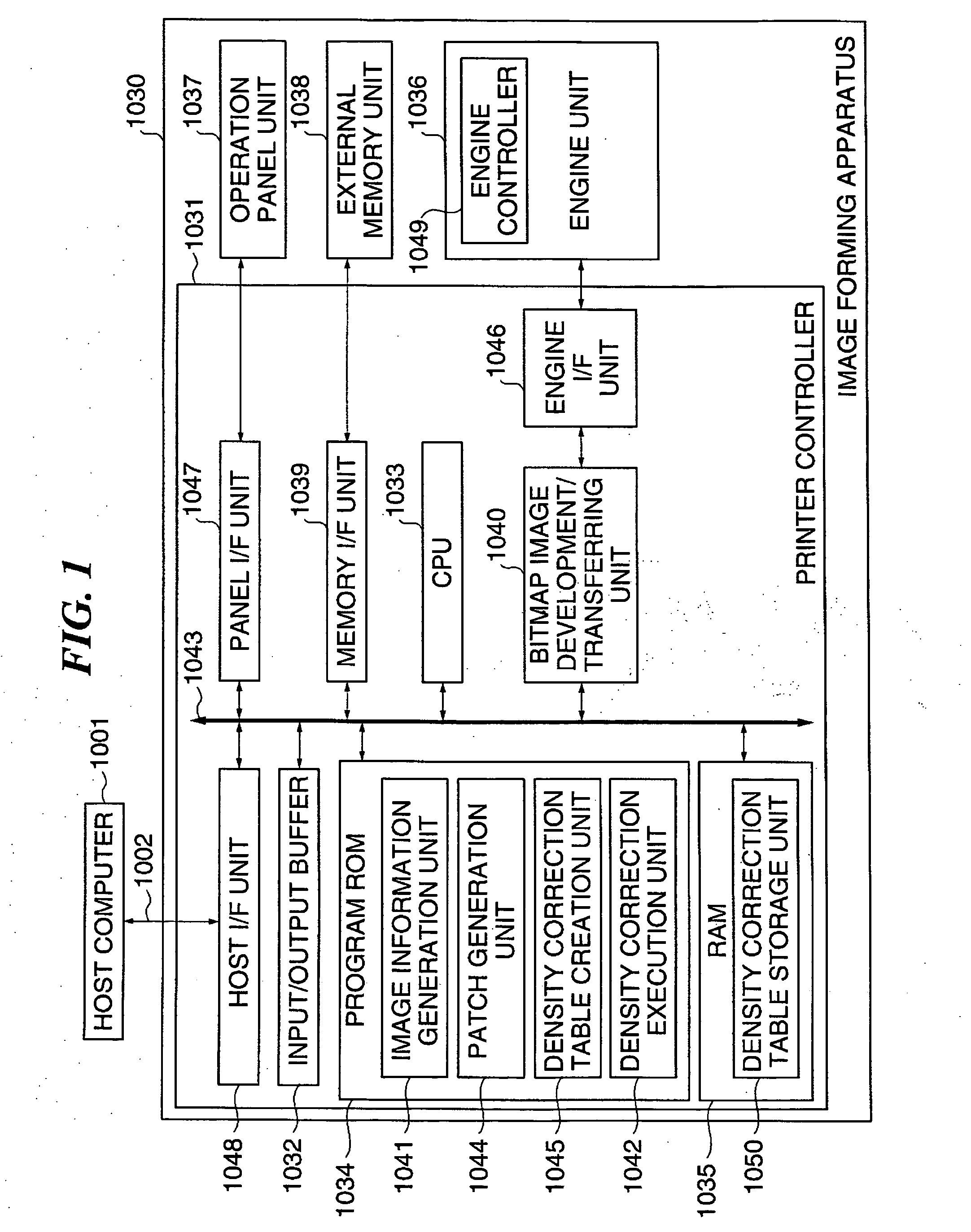
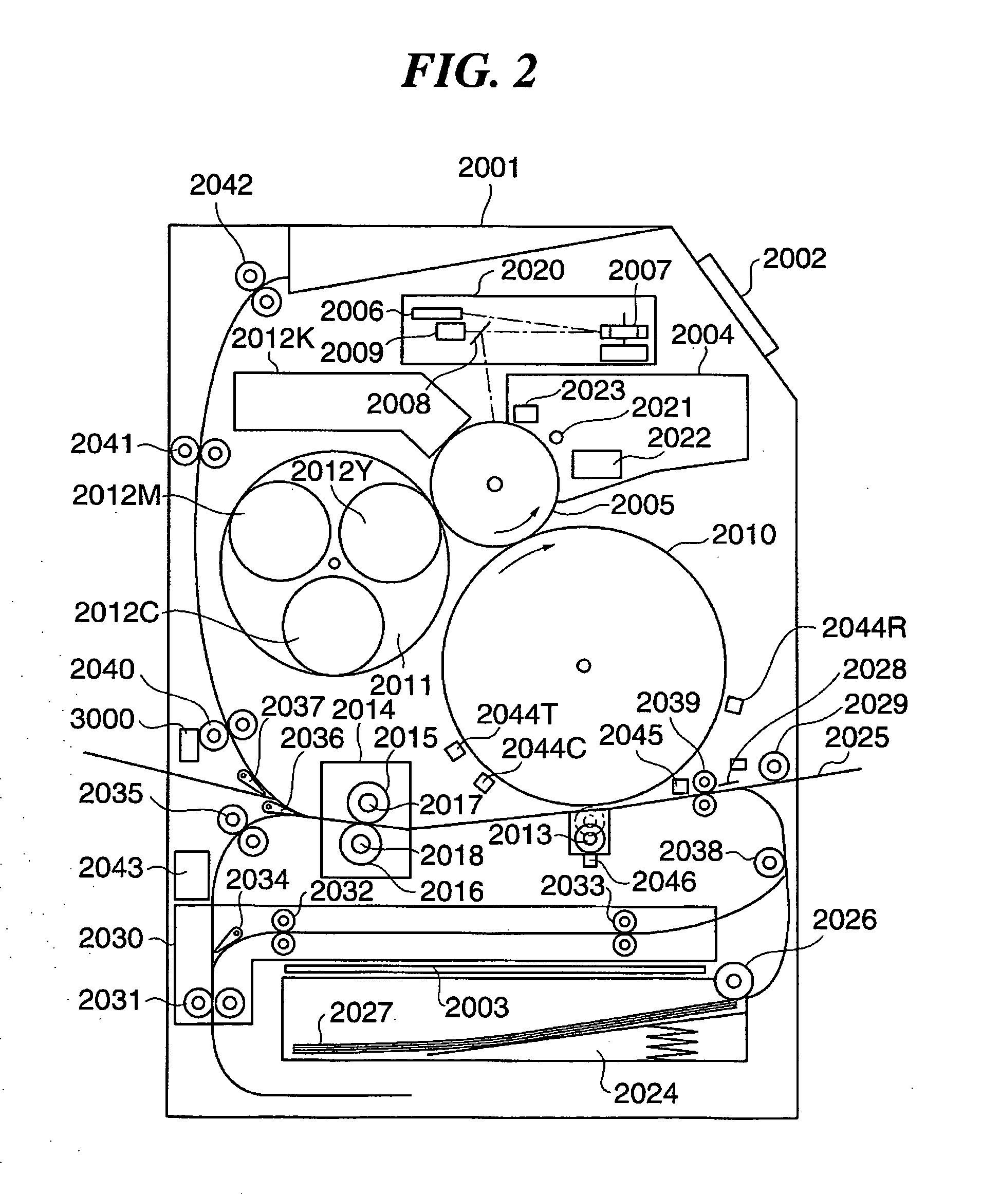
[0050]FIG. 1 is a block diagram schematically showing the construction of a substantial part of an image forming apparatus according to the present invention.

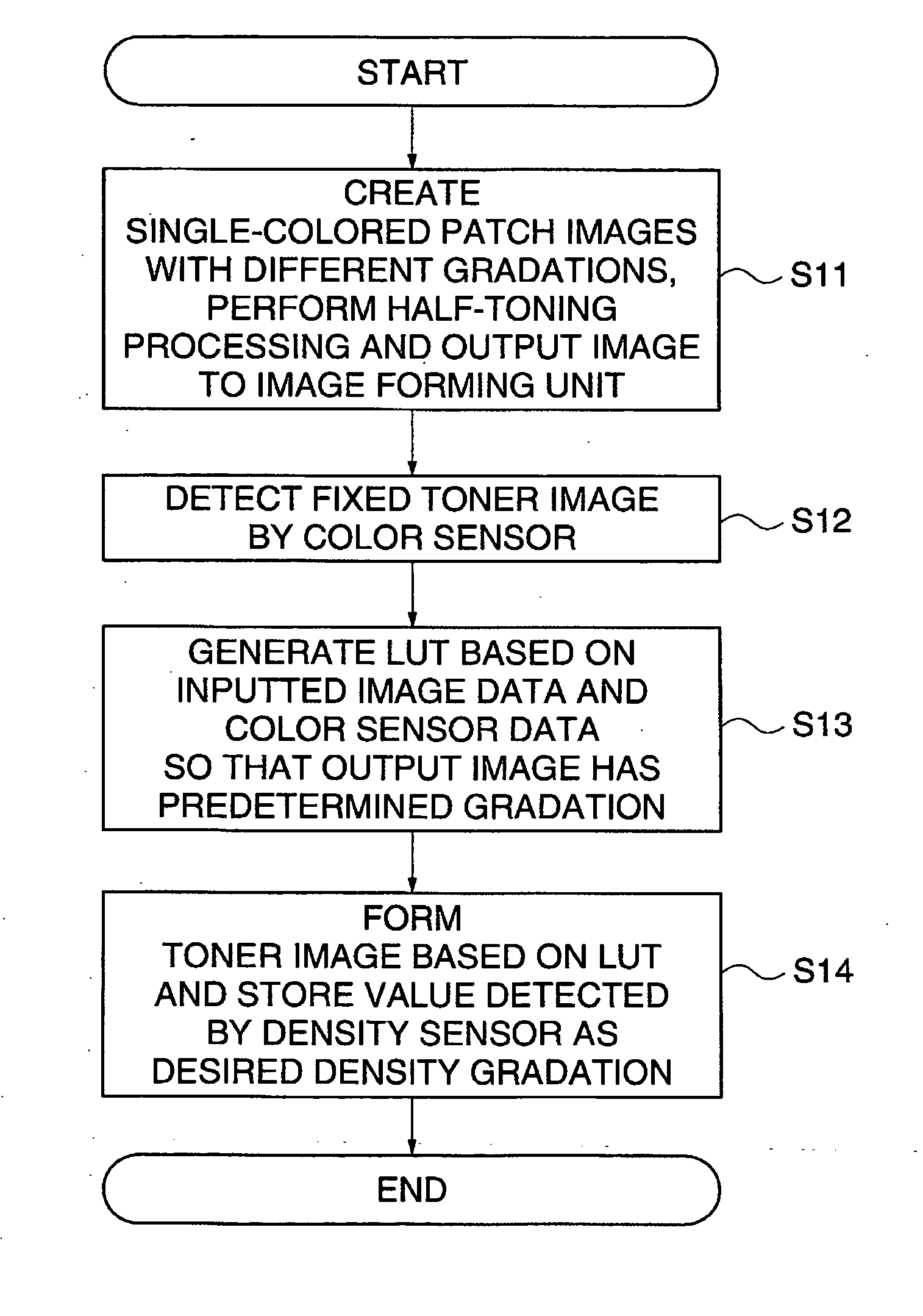
[0051] In the present embodiment, a control method of an image forming apparatus will be described, in which trigger bars of new concept and toner patch images are formed on a transfer material in a plurality of colors and an accurate read timing of toner patch images for a color sensor is generated, the color sensor being disposed on a conveying path located downstream of a fixing device.

[0052] Further, in the present embodiment, an electronic photographic image forming apparatus will be described by way of example. An ink jet image forming apparatus and an sublimation image forming apparatus also have the same problems as in the electronic photographic image forming apparatus, however such problems can be solved by the control method described below. That is to say, the present invention can be applied to various types of im...


PUM


Abstract

An image forming apparatus that is capable of generating highly accurate read timing of a patch image, thereby achieving highly accurate density adjustment and improving color stability. A patch image for color adjustment is read in read timing generated when a trigger bar is detected. The patch image and the trigger bar that are to be read by a color sensor are formed on a transfer material. Image formation is executed by a printer controller in an image forming condition set differently for the trigger bar and for the patch image.

Description

BACKGROUND OF THE INVENTION [0001] 1. Field of the Invention [0002] This invention relates to an image forming apparatus for a printer or a copying machine which forms an image using techniques such as an electronic photographic technique or an inkjet technique, and a control method of the image forming apparatus. [0003] 2. Description of the Related Art [0004] In recent years, there is increasing demand for direct imaging printer which does not need a printing plate used in off-set printing or the like. Many companies use direct imaging printers in order to reduce time required for printing, realize services adapted for individual customers, satisfy the demand for mass-printing, and address environmental problems involving discard of sheets with printing errors. Among the direct imaging printers, the ink jet printer suitable for photographic printing, which is advantageous in prices, and the electronic photographic printer, which is high in productivity and near to the offset print...

Claims


Application Information

Patent Timeline
IPC IPC(8): G03G15/00
CPCG03G15/5033G03G2215/00042G03G2215/00059G03G2215/0177G03G15/0131G03G15/5058
Inventor ITAGAKI, TOMOHISA
Owner CANON KK
Why Eureka
Try Eureka