Perpendicular magnetic recording medium and magnetic storage apparatus

a magnetic recording medium and perpendicular magnetic technology, applied in the field of perpendicular magnetic recording media and magnetic storage apparatuses, can solve the problems of inability to form minute recording bits in the recording layer, inability to increase the recording density, and inability to maintain the magnetic stability of the recorded magnet, so as to prevent the spread of magnetic flux and the eradication of adjacent tracks. , to narrow the width of the transition region of magnetization, the effect of increasing the density of the track

Inactive Publication Date: 2006-09-07
SHOWA DENKO KK
View PDF15 Cites 35 Cited by
  • Summary
  • Abstract
  • Description
  • Claims
  • Application Information

AI Technical Summary

Benefits of technology

[0045] According to the present invention, the magnetic flux control layer of the superconduction state becomes a perfect diamagnetic state, and the magnetic flux from the recording head is interrupted by the magnetic flux control layer. It is possible to change a part of the magnetic flux control layer to normal conduction state by applying heat, and thus, it becomes possible to cause the magnetic flux to pass selectively through the region thus changed to normal conduction state. Thereby, there is caused concentration of the magnetic flux in such a re

Problems solved by technology

However, there has been caused the problem of thermal stability of recorded magnetization in the technology of in-plane magnetic recording when the recording unit is miniaturized beyond the recording density of 100 Gbit/in2.
Thereby, the magnetic flux is diffused at the surface of the recording layer, and there arises a problem that it becomes not possible to form minute recording bits in the recording layer.
Because of this, it has not been possible to increase the recording density.
Because the magnetic particles of the recording layer are formed on a non-magnetic intermediate laye

Method used


Image

  • Perpendicular magnetic recording medium and magnetic storage apparatus
  • Perpendicular magnetic recording medium and magnetic storage apparatus
  • Perpendicular magnetic recording medium and magnetic storage apparatus

Examples


example 2

[0113] Example 2 is similar to Example 1 except that the under layer: NiFe film (5 nm) is formed between the first seed layer: Ta film (5 nm) and the magnetic flux slit layer: NiFe film (5 nm), by setting the ambient gas pressure to 0.5 Pa.

COMPARATIVE EXAMPLE 1

[0114] Comparative Example 1 is similar to that of Example 1 except that the magnetic flux slit layer: NiFe film (5 nm) of Example 1 is formed by setting the ambient gas pressure to 0.5 Pa.

[0115]FIG. 4 is a diagram showing the characteristics of the perpendicular magnetic recording media according to Examples 1, 2 and Comparative Example 1, wherein α in the drawing represents the gradient 4π×ΔM / H of the magnetization curve observed by applying a magnetic field to the recording layer in the perpendicular direction for the part near the coercive force. The closer α is to one, the more the magnetic particles have been isolated magnetically.

[0116] Referring to FIG. 4, it can be seen that Comparative Example provides the value ...

example 3

[0120] A perpendicular magnetic recording medium of the following construction was manufactured as the perpendicular magnetic recording medium of the present embodiment. Thus, starting from the side of the substrate, the construction includes glass substrate / soft-magnetic backing layer: CoNbZr film (190 nm) / magnetic flux slit layer: CoNbZr film (10 nm) / seed layer: Ta film (2 nm) / non-magnetic intermediate layer: Ru film (15 nm) / recording layer: (Co71Cr9Pt20) 90 vol %-(SiO2) 10 vol % film (10 nm) / protective film: carbon (4 nm) / lubricating film: AM3001 film (1.5 nm). The films except for the lubricating layer were formed by using a sputtering apparatus of Ar gas ambient, wherein the CoNbZr film for the soft-magnetic backing layer and the Ta film were formed by setting the ambient gas pressure to 0.5 Pa, while the CoNbZr film for the magnetic flux slit layer and the Ru film were formed by setting the ambient gas pressure to 4.0 Pa.

second embodiment

[0123] Next, a perpendicular magnetic recording medium of the second embodiment of the present invention will be explained, wherein it should be noted that, in the second embodiment, the non-magnetic particles and the magnetic particles are separated in the non-magnetic intermediate layer and the recording layer in the state surrounded by a non-soluble phase.

[0124]FIG. 6 is a schematic cross-sectional diagram of the perpendicular magnetic recording medium according to the second embodiment of the present invention, wherein those parts corresponding to the parts explained previously are designated by the same reference numerals and the description thereof will be omitted.

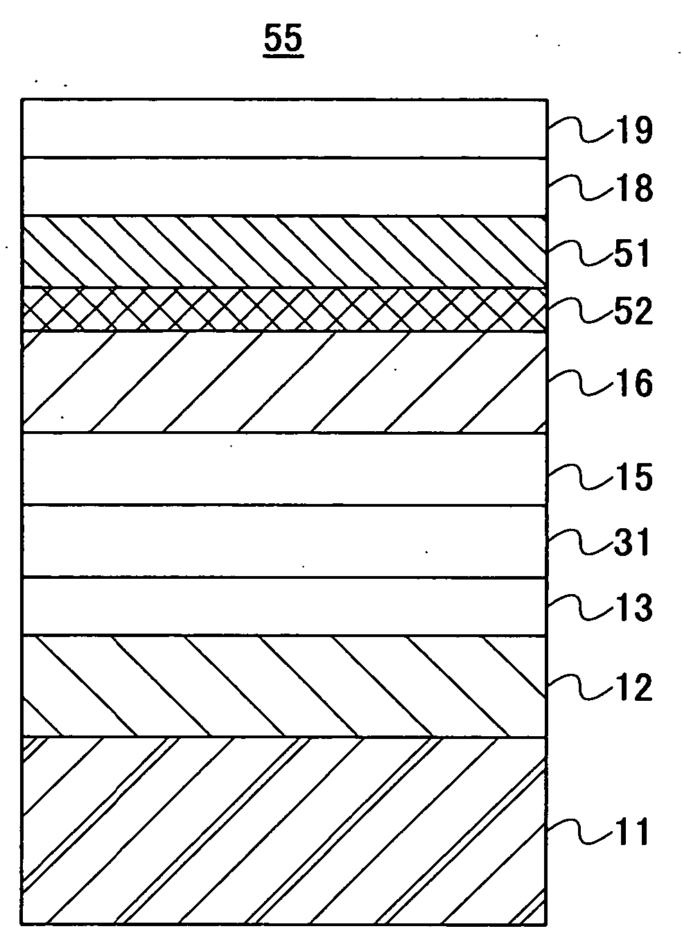
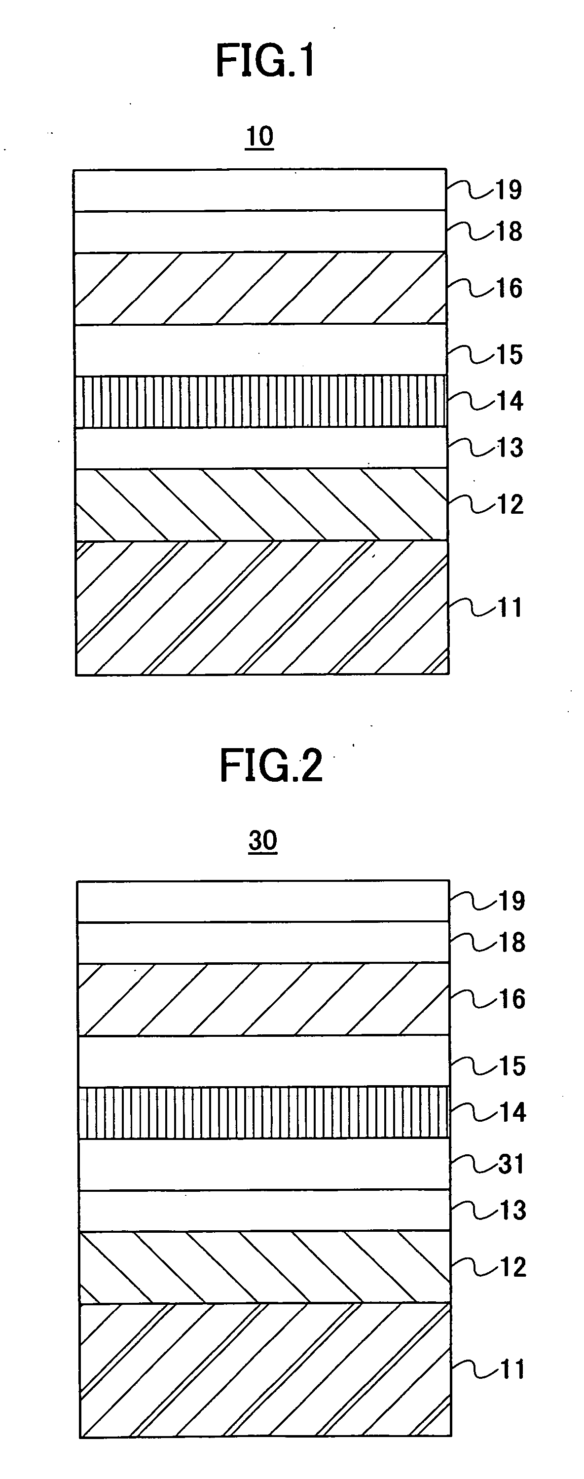
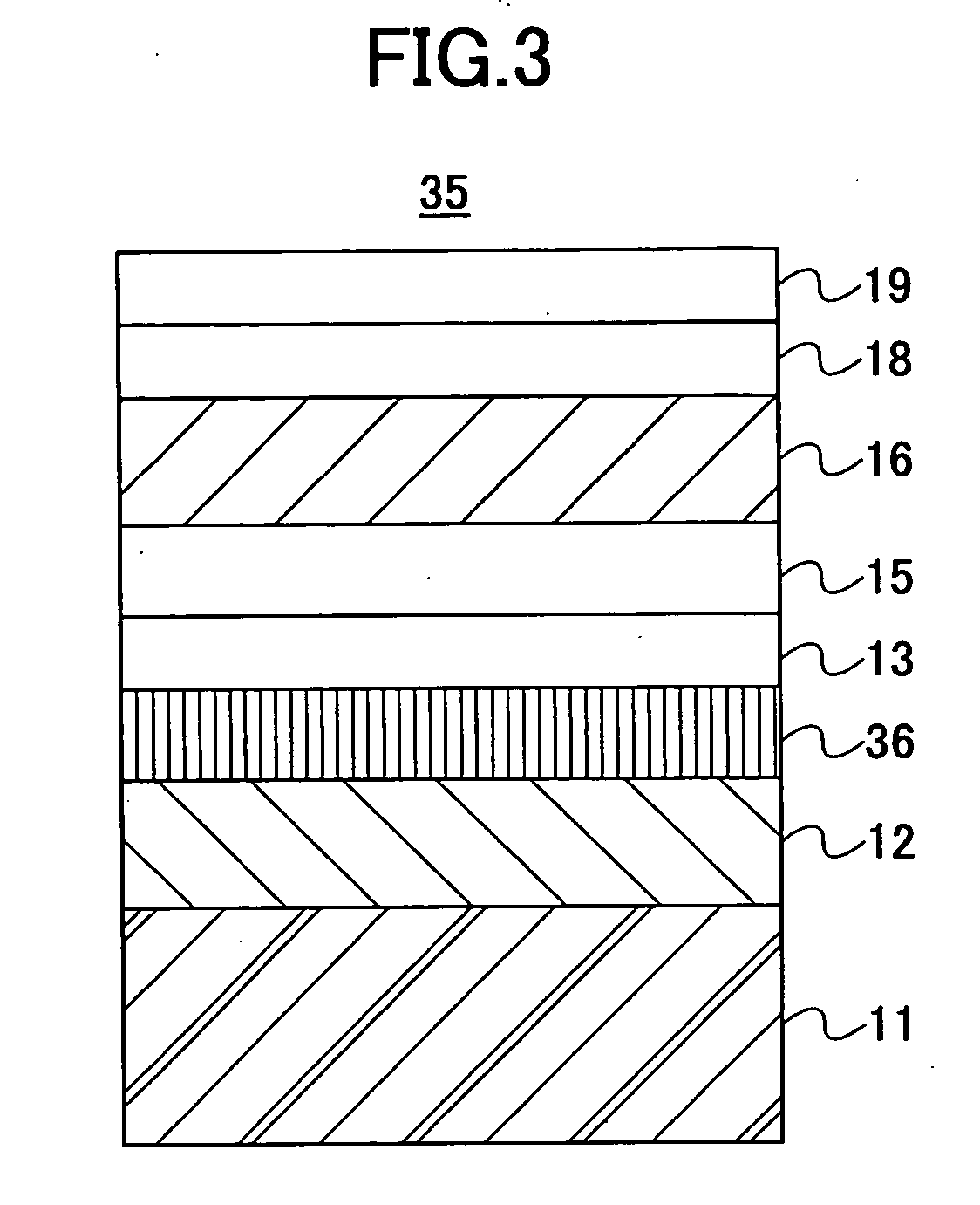
[0125] Referring to FIG. 6, the perpendicular magnetic recording medium 40 of the present embodiment includes a substrate 11 and has a construction in which a soft-magnetic backing layer 12, a seed layer 13, an under layer 31, a non-magnetic intermediate layer 41, a recording layer 46, a protective layer 18, and a ...


PUM


Abstract

A perpendicular magnetic recording medium includes a substrate and has a construction to stack consecutively on the substrate, a soft-magnetic backing layer, a seed layer, a magnetic flux slit layer, a non-magnetic intermediate layer, a recording layer, a protective layer, and a lubricating layer, wherein the magnetic flux slit layer 13 includes soft-magnetic particles of generally columnar structure having a boundary part of a non-magnetic part and constricts the magnetic flux from the recording head only to the part where the soft-magnetic particle is provided and suppresses thereby spreading of the magnetic flux. Further, a perpendicular magnetic recording medium carrying a magnetic flux slit layer over the recording layer is disposed.

Description

CROSS-REFERENCE TO RELATED APPLICATIONS [0001] The present invention is a continuation application filed under 35 U.S.C. 111(a) claiming benefit under 35 U.S.C. 120 and 365(c) of PCT application JP2003 / 012538 filed on Sep. 30, 2003, the entire contents of each are incorporated herein as reference.BACKGROUND OF THE INVENTION [0002] The present invention relates to perpendicular magnetic recording media and magnetic storage apparatuses, and more particularly to a perpendicular magnetic recording medium and a magnetic storage apparatus capable of performing high density recording. [0003] With rapid development of technology in magnetic storage apparatuses, practical machine of surface recording density of about 100 G bit / in2 is about to be commercialized by using the technology of in-plane recording, in which recording is made on a magnetic recording medium in an in-plane direction. However, there has been caused the problem of thermal stability of recorded magnetization in the technol...

Claims


Application Information

Patent Timeline
IPC IPC(8): G11B5/66B05D5/12G11B5/65G11B5/667G11B5/73
CPCG11B5/667G11B5/7325G11B5/7368G11B5/737G11B5/7373G11B5/7377
Inventor SUGIMOTO, TOSHIOINAMURA, RYOSAKUTANAKA, ATSUSHI
Owner SHOWA DENKO KK
Why Eureka
Try Eureka