Software defined radio and library configuration therefor

a software defined radio and library technology, applied in the field of software defined radio, can solve the problems of insufficient security or scalability in the connection between the libraries such as the second time the library appears, the assignment of control signals to bits, and the inability to receive correct control information, etc., to achieve high reusability, reduce the number of control signals between libraries, and facilitate the connection between libraries.

Inactive Publication Date: 2006-09-07
HITACHI LTD
View PDF6 Cites 15 Cited by
  • Summary
  • Abstract
  • Description
  • Claims
  • Application Information

AI Technical Summary

Benefits of technology

[0020] In the first arrangement of the present invention, the same library is not used a plurality of times in the same system, and when the use order of libraries can be previously predicted, the exchange, insertion and deletion of a library can be realized without modifying the library core for performing essential processing operation of the library. In the second arrangement; the exchange, insertion and deletion of a library can be realized even under conditions excluded in the first arrangement. In this way, a flexibility in the connection between libraries can be secured as a first effect. In the third arrangement, the number of control signals between libraries can be reduced, in addition to the first effect. A fourth arrangement can have the structure of a selector smaller in size than that in the second arrangement. A fifth arrangement can have the structures of a converter and an inverter smaller in size than those in the third arrangement. Thus the reduction of the installation scale can be realized as a second effect. Due to the first effect, the radio communication system can be realized in the form of a combination of libraries having a high reusability, the number of steps of developing the software defined radio can be reduced, and its cost can be decreased. Due to the second effect, an increase in the scale involved by versatilization can be minimized, and application to a car-mounted terminal or a radio base station can be realized.

Problems solved by technology

However, only by preparing the common interface, a flexibility or scalability in the connection between the libraries such as addition, deletion, exchange, etc. of a library cannot be secured to a sufficient extent.
Thus a problem takes place, when the above control signal assigning method and control signal transmitting method are used, when the library is shared by a plurality of systems, when the library is exchanged, or when the library is used several times in the same system.
However, since the CRC library has an interface which receives the head and tail of the data at the control bits b0 and b1, the library appearing for the second time cannot receive correct control information.
As mentioned above, when a library having a common interface is used a plurality of times in the same system, a problem with how to assign the control signal to the bit takes place.

Method used


Image

  • Software defined radio and library configuration therefor
  • Software defined radio and library configuration therefor
  • Software defined radio and library configuration therefor

Examples


embodiment 1

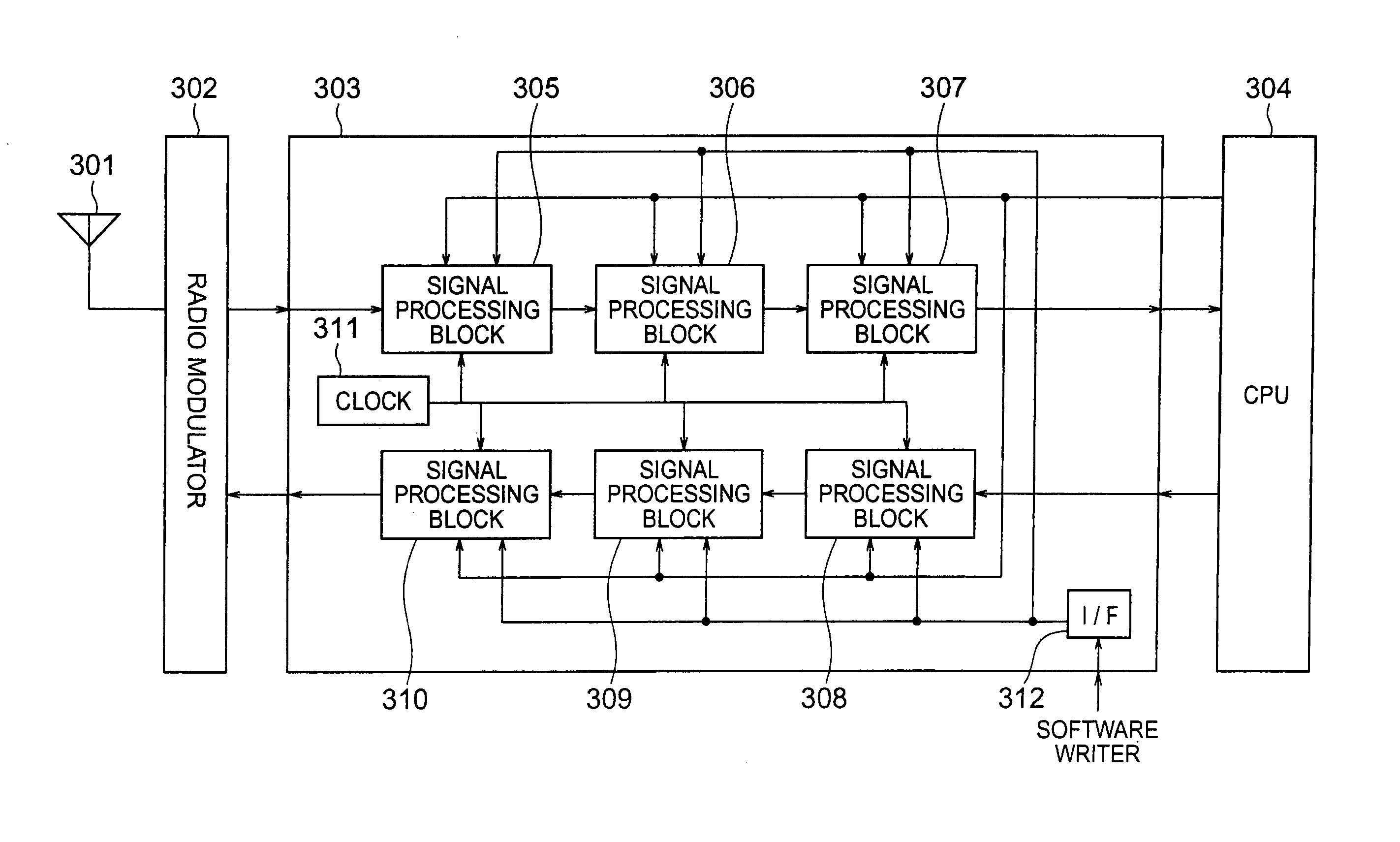
[0043]FIG. 4 shows a first arrangement of a signal processing library to be installed to each signal processing block, which library can solve the first problem. The signal processing blocks 305 to 310 in FIG. 3 are configured and wired on the basis of the configuration data described in the signal processing library. It is assumed that a single signal processing library is basically realized in the form of a single signal processing block. In this arrangement, data is input to the signal processing library 401 together with a control signal indicative of control information on the data. The signal processing library 401 includes a signal processing library core 402. The signal processing library core performs essential part of the signal processing operation to be desirably realized by the library; and does not generate the control signal, nor reposition the control bits of the control signal, which are not the essential part thereof. For example, modulation is carried out by mappi...

embodiment 2

[0047]FIG. 6 shows a second arrangement of the signal processing library to be installed to each of the signal processing blocks 305 to 310. This arrangement corresponds to the first arrangement, except that a selector 603 is added in the signal processing library of the first arrangement. The selector 603 is formed on such a reconfigurable device as an FPGA similarly to a signal processing library core 602. In this arrangement, data is input to a signal processing library 601 together with a communication system indicative of control information on the data. The control bits of the control signal received at the signal processing library are repositioned at the selector 603 into a control bit array necessary for the signal processing library core. Linking between the control signals at the input and output of the selector is carried out based on select information. Although the selector 603 is placed on the upstream side of the signal processing library core 602 in this example, it...

embodiment 3

[0051]FIG. 8 shows a third arrangement of the signal processing library. In this arrangement, an identifier is transmitted between signal processing libraries 801. The identifier is control information including timing information or identification information on the timing. The identifier will be explained more in detail later. The identifier input to the signal processing library 801 is converted by an identifier converter 803 to a control signal including information about control bits necessary for a signal processing library core 802. The conversion assignment is carried out by using a conversion mask and a conversion value. Setting of the conversion mask and value is carried out suitably by the CPU 304, when the communication system to be realized was modified or when the same communication system was used but its encoding system or the like was modified. Control signals issued from the core are converted by an identifier inverter 804 to an identifier and then transmitted to a...


PUM


Abstract

A radio communication apparatus having a radio modem for processing a signal in a radio frequency band, a signal processor for processing a base band of a transmission or reception signal, and a CPU for processing a protocol. The signal processor includes signal processing blocks implemented by programmable software. Each of the signal processing blocks processes a signal of reception signal data input from the radio modem or from a preceding stage of one of the signal processing blocks or a signal of transmission signal data input from the CPU or from the preceding stage of signal processing block on the basis of a control signal input together with the transmission signal data or the reception signal data. The control signal can include information required by all the signal processing blocks in a common format.

Description

CROSS-REFERENCE TO RELATED APPLICATIONS [0001] The present application relates to subject matters described in U.S. patent application publication No. 2005 / 0272464A1 (application Ser. No. 11 / 097,293 filed on Apr. 4, 2005) assigned to the assignee of the present application, application Ser. No. 11 / 209,713 filed on Aug. 24, 2005 assigned to the assignee of the present application, and application Ser. No. 11 / 218,484 filed on Sep. 6, 2005 assigned to the assignee of the present application. The disclosures of these applications are incorporated herein by reference.INCORPORATION BY REFERENCE [0002] The present application claims priority from Japanese application JP 2005-059857 filed on Mar. 4, 2005, the content of which is hereby incorporated by reference into this application. BACKGROUND OF THE INVENTION [0003] The present invention relates to a software defined radio in which a software library is controlled by distributed control scheme. [0004] As broadband communication is spread,...

Claims


Application Information

Patent Timeline
Patent Type & Authority Applications(United States)
IPC IPC(8): H04B1/40
CPCH04B1/0003H04B1/40
Inventor ISHIKAWA, TAKASHIKAWABE, MANABUTSUNEHARA, KATSUHIKOISHII, HIROTAKE
Owner HITACHI LTD
Why Eureka
Try Eureka