Cardiac tissue ablation instrument with flexible wrist

a wrist and wrist technology, applied in the field of wrist mechanisms of surgical tools, can solve the problems millions of dollars annually in hospital residency costs alone, and reducing the cost of hospitalization, and achieving the effect of saving millions of hospital days and millions of dollars

Inactive Publication Date: 2006-09-07
INTUITIVE SURGICAL OPERATIONS INC
View PDF18 Cites 1105 Cited by
  • Summary
  • Abstract
  • Description
  • Claims
  • Application Information

AI Technical Summary

Benefits of technology

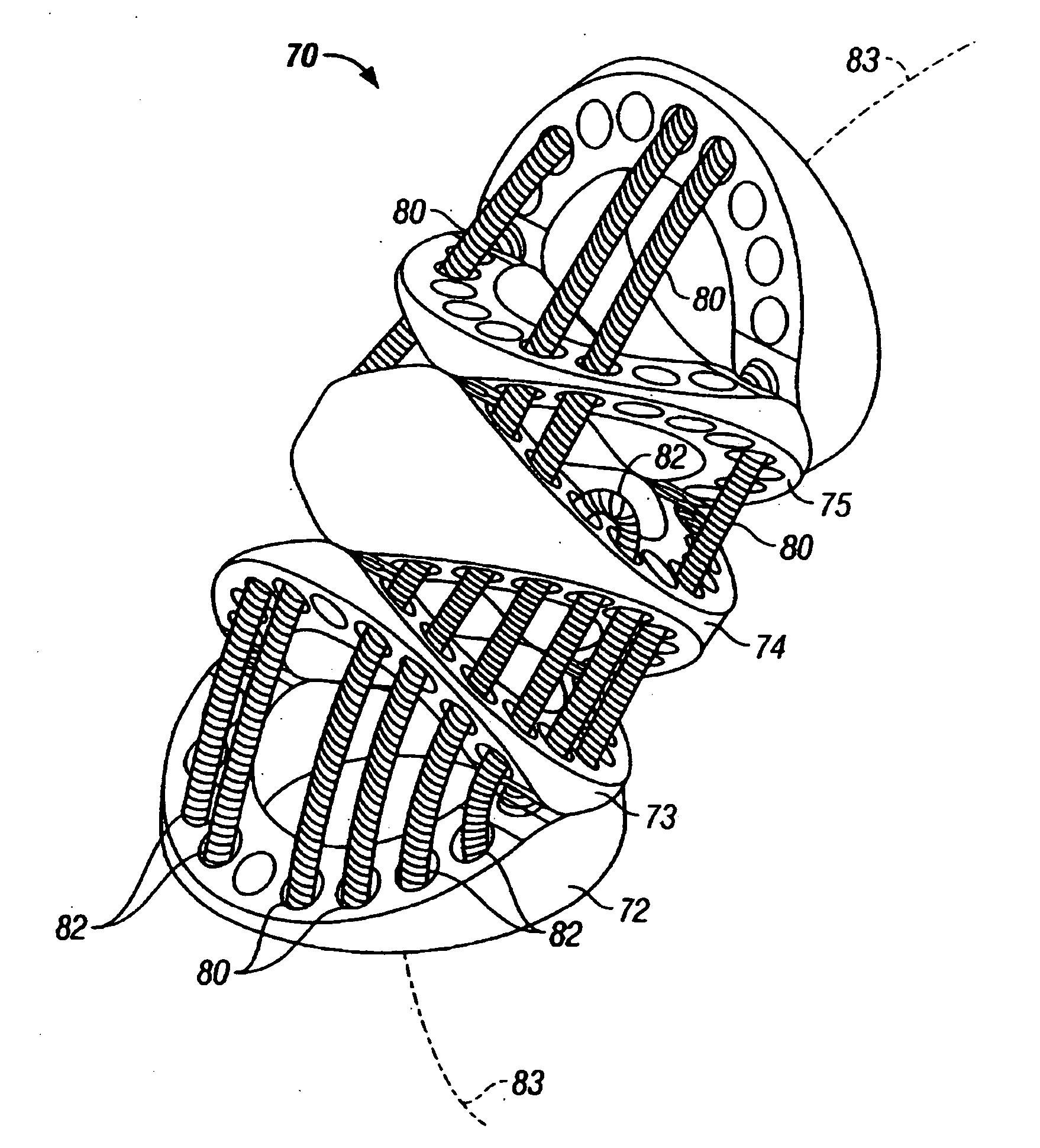
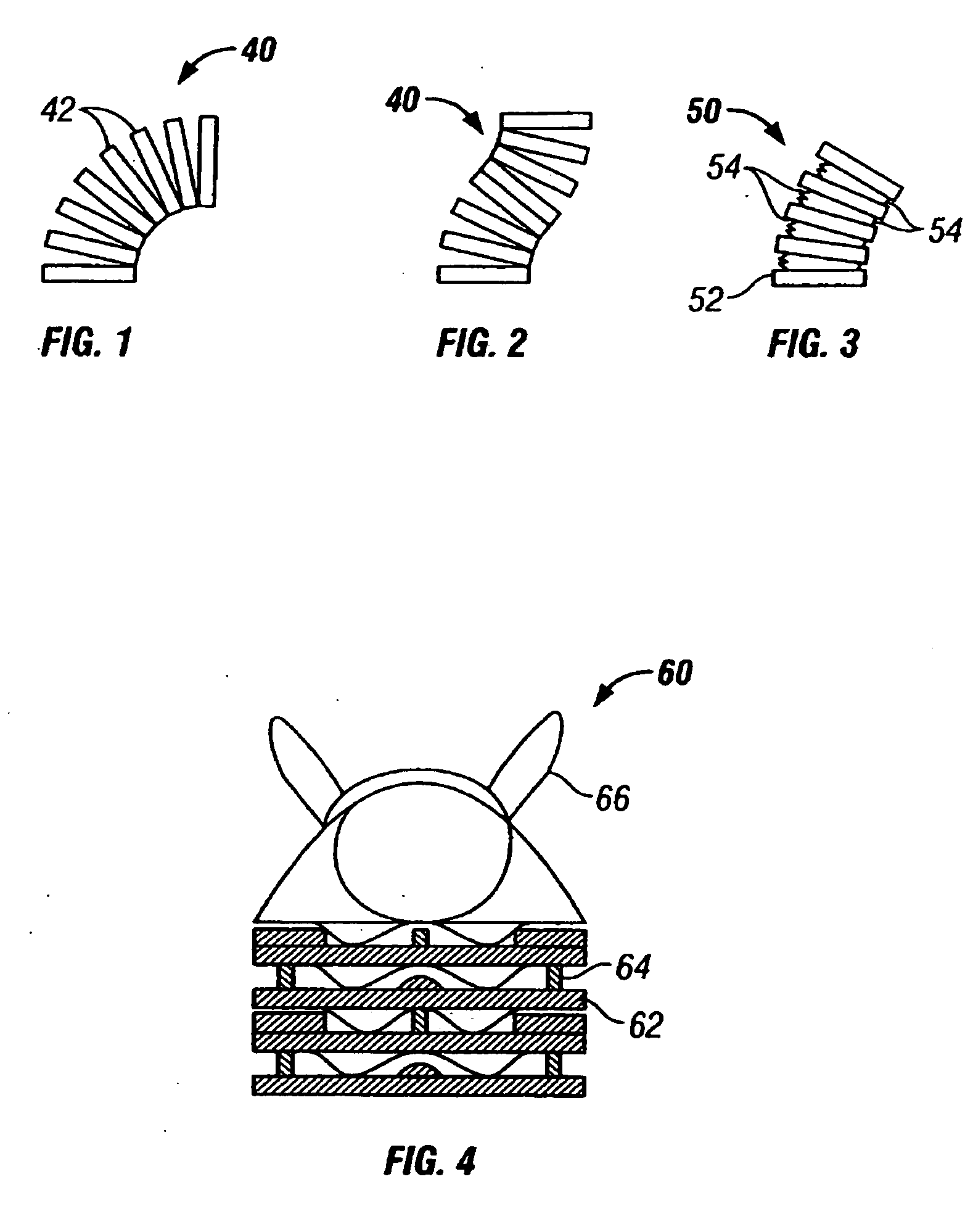
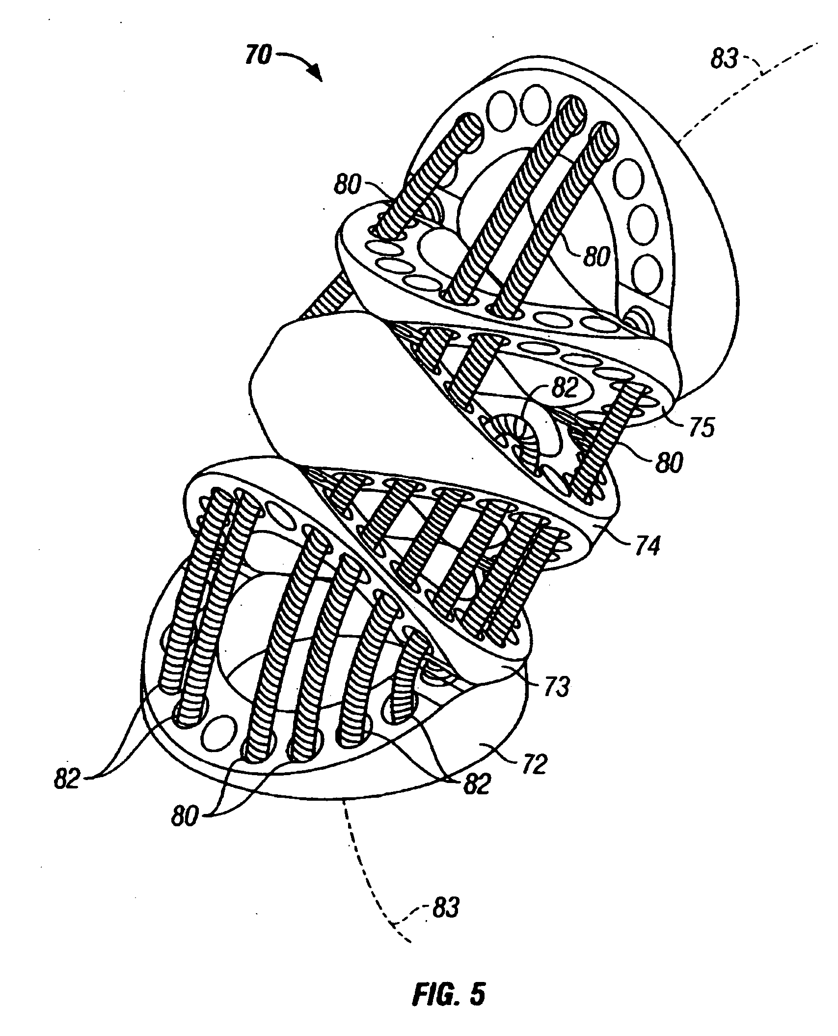
[0031] As is described below with respect to particular embodiments, shaped contact surfaces may be included such that nonattached rolling contact may permit pivoting of the adjacent disks, while balancing the amount of cable motion on opposite sides of the disks. In addition, the nonattached contact aspect of the these exemplary embodiments promotes convenient, simplified manufacturing and assembly processes and reduced part count, which is particularly useful in embodiments having a small overall wrist diameter.
[0035] Embodiments including a cable actuator assembly having aspects of the invention provide to the simultaneous actuation of a substantial plurality of cables, and provide for a predetermined proportionality of motion of a plurality of distinct cable sets. This capability is provided with a simple, inexpensive structure which avoids highly complex control mechanisms. As described further below, for a given total cross-sectional area in each cable set and a given overall disk diameter, a mechanically redundant number of cables permits the cable diameter to be smaller, permits increasing the moment arm or mechanical advantage of the cables, and permits a larger unobstructed longitudinal center lumen along the centerline of the disks. These advantages are particularly useful in wrist members built to achieve the very small overall diameter such as are currently used in endoscopic surgery.
[0037] In specific embodiments, the back end mechanism is configured to allow for the replacement of the end effector, the wrist, and the shaft of the surgical instrument with relative ease.
[0044] In accordance with another aspect of the present invention, a minimally invasive surgical instrument has an end effector which comprises a grip support having a left pivot and a right pivot. A left jaw is rotatable around the left pivot of the grip support and a right jaw is rotatable around the right pivot of the grip support. A left slider pin is attached to the left jaw and spaced from the left pivot pin, and a right slider pin is attached to the right jaw and spaced from the right pivot pin. A slotted member includes a left slider pin slot in which the left slider pin is slidable to move the left jaw between an open position and a closed position, and a right slider pin slot in which the right slider pin is slidable to move the right jaw between an open position and a closed position. A slider pin actuator is movable relative to the slotted member to cause the left slider pin to slide in the left slider pin slot and the right slider pinto slide in the right slider pin slot, to move the left jaw and the right jaw between the open position and the closed position.
[0050] In accordance with other aspects of the present invention, a method and apparatus are provided to further facilitate the safe placement and provide visual verification of the ablation catheter or other devices in CTA treatments.

Problems solved by technology

Thus, an increased adoption of minimally invasive techniques could save millions of hospital days, and millions of dollars annually in hospital residency costs alone.
There are many disadvantages relating to current minimally invasive surgical (MIS) technology.
For example, existing MIS instruments deny the surgeon the flexibility of tool placement found in open surgery.
Most current laparoscopic tools have rigid shafts, so that it can be difficult to approach the worksite through the small incision.
Additionally, the length and construction of many endoscopic instruments reduces the surgeon's ability to feel forces exerted by tissues and organs on the end effector of the associated tool.
The lack of dexterity and sensitivity of endoscopic tools is a major impediment to the expansion of minimally invasive surgery.
As a result, blood is not pumped completely out of them causing the blood to potentially pool and clot.
If a portion of a blood clot in the atria leaves the heart and becomes lodged in an artery in the brain, a stroke results.
Minimally invasive CTA treatment is a manually difficult procedure because the ablation catheter needs to be blindly maneuvered around internal organs, tissues, body structures, etc. and placed at the appropriate pulmonary veins before the energized ablation process can begin.
Moreover, the pulmonary veins that need to be reached are often hidden from view behind anatomy which often can not be seen which makes the safe placement and visual verification of the ablation catheter or other devices extremely challenging.
While minimally invasive surgical robotic systems have proven to be valuable in enabling CTA treatments to be performed more expeditiously, the instruments currently available for minimally invasive surgical robotic systems does not provide sufficient visual verification needed for safer and more accurate placement of ablation and other position sensitive devices when such placement is hidden behind an anatomy.

Method used


Image

  • Cardiac tissue ablation instrument with flexible wrist
  • Cardiac tissue ablation instrument with flexible wrist
  • Cardiac tissue ablation instrument with flexible wrist

Examples


Embodiment Construction

[0149] As used herein, “end effector” refers to an actual working distal part that is manipulable by means of the wrist member for a medical function, e.g., for effecting a predetermined treatment of a target tissue. For instance, some end effectors have a single working member such as a scalpel, a blade, or an electrode. Other end effectors have a pair or plurality of working members such as forceps, graspers, scissors, or clip appliers, for example. In certain embodiments, the disks or vertebrae are configured to have openings which collectively define a longitudinal lumen or space along the wrist, providing a conduit for any one of a number of alternative elements or instrumentalities associated with the operation of an end effector. Examples include conductors for electrically activated end effectors (e.g., electrosurgical electrodes; transducers, sensors, and the like); conduits for fluids, gases or solids (e.g., for suction, insufflation, irrigation, treatment fluids, accessor...


PUM


Abstract

An articulate minimally invasive surgical instrument with a flexible wrist to facilitate the safe placement and provide visual verification of the ablation catheter or other devices in Cardiac Tissue Ablation (CTA) treatments is described. In one embodiment, the instrument is an endoscope which has an elongate shaft, a flexible wrist at the working end of the shaft, and a vision scope lens at the tip of the flexible wrist. The flexible wrist has at least one degree of freedom to provide the desired articulation. It is actuated and controlled by a drive mechanism located in the housing at the distal end of the shaft. The articulation of the endoscope allows images of hard-to-see places to be taken for use in assisting the placement of the ablation catheter on the desired cardiac tissue. The endoscope may further include couplings to releasably attach an ablation device / catheter or a catheter guide to the endoscope thereby further utilizing the endoscope articulation to facilitate placement of the ablation catheter on hard-to-reach cardiac tissues. In another embodiment, the articulate instrument is a grasper or any other instrument with a flexible wrist and a built-in lumen to allow an endoscope to insert and be guided to the distal end of the instrument.

Description

CROSS-REFERENCE TO RELATED APPLICATIONS [0001] This application is a continuation-in-part of U.S. patent application Ser. No. 11 / 071,480, filed Mar. 3, 2005, which is a continuation-in-part of U.S. patent application Ser. No. 10 / 726,795, filed Dec. 2, 2003, which claims priority from provisional patent application Ser. No. 60 / 431,636, filed on Dec. 6, 2002, the disclosures of which are incorporated by reference herein in their entireties. This application is also a continuation-in-part of U.S. patent application Ser. No. 10 / 980,119, filed Nov. 1, 2004, which is a divisional of U.S. patent application Ser. No. 10 / 187,248, filed Jun. 28, 2002, now U.S. Pat. No. 6,817,974, which claims priority from provisional application Ser. No. 60 / 327,702, filed Oct. 5, 2001, and Ser. No. 60 / 301,967, filed Jun. 29, 2001, the disclosures of which are incorporated by reference herein in their entireties. [0002] This application is also related to the following patents and patent applications, the ful...

Claims


Application Information

Patent Timeline
Patent Type & Authority Applications(United States)
IPC IPC(8): A61B1/00
CPCA61B1/00142A61B1/00149A61B1/0052A61B1/0055A61B1/0058A61B1/008A61B1/018A61B19/22A61B19/2203A61B19/5212A61B2017/00243A61B2017/00309A61B2017/00323A61B2019/2211A61B2019/2226A61B2019/2234A61B2019/2238A61B2019/2242A61B2019/2246A61B2034/715A61B34/70A61B34/71A61B2034/301A61B90/361A61B34/30A61B2034/304A61B2034/305A61B2034/306
Inventor IKEDA, MICHAEL H.ROSA, DAVID J.COOPER, THOMAS G.ANDERSON, S. CHRISTOPHER
Owner INTUITIVE SURGICAL OPERATIONS INC
Why Eureka
Try Eureka