Orthopedic plate

a technology of orthopedic plate and plate body, which is applied in the field of orthopedic plate, can solve the problems of screw interference, more individual variations, and more problems in the implanting process, and achieve the effect of improving the function of ligaments and tendons, and preventing the growth of bone cells

Active Publication Date: 2006-09-07
ORTHOHELIX SURGICAL DESIGNS
View PDF31 Cites 72 Cited by
  • Summary
  • Abstract
  • Description
  • Claims
  • Application Information

AI Technical Summary

Benefits of technology

[0009] The plate has a central trunk portion including one or more screw holes separated by a waist shaped linking portion along a longitudinal axis and a set of upper and lower arms including screw holes which are placed at a radially equal distance but which diverge asymmetrically from the longitudinal axis to avoid conflicts in the screw placement of the paired arm, specifically, so that the screws of a set of arms do not impinge on each other. The plate is radiused with a curvature corresponding generally to the curvature of a bony surface. The upper pair of arms, and the lower pair of arms continue this curvature and the through holes are placed so that the angle of the longitudinal axis of the screws converge in the direction of the distal end of the screw. The screw holes are placed with the longitudinal axis perpendicular a tangent to the top surface of the arm with the effect that the longitudinal axes of the screws converge in the direction of the distal end. This increases the pull-out strength of the screws. Further the screw holes are concavely rounded to allow for multi-axis orientation of the low profile, rounded screw in the hole, which can be oriented with a conical shape about the longitudinal axis of the screw hole having an angle of at least 20°, preferably at least 25°, and most preferably about 30°.
[0010] The screws do not in fact conflict since each of the arms in a pair form a different angle to the central trunk so that the longitudinal axis of the screws are offset from each other along the length of the plate. The pre-bent configuration of the plate is designed to increase operating room efficiency by facilitating commonly desirable shapes while maintaining the required strength and by permitting bending without deforming the screw holes. This results in making customization in anticipation or during surgery easier.
[0011] The screws useful with the plate of the present invention are self-starting, self-tapping screws including the option of partial or full cannulation. The screws include a cutting end having multiple flutes, and preferably 2 or 3 flutes about a conical recess. The screws further include a partial taper of the inner diameter in the proximal end over the first several thread,turns, for example over 2-8, and preferably over 3-5 turns in order to increase the fatigue life of the screw as well as providing potential physiological advantages in use. The screw head is a rounded low profile head. The screws further include a torque driving recess that may be a hexagon, a torx shape, or a modification of a torx shape, i.e. a multilobe shape having from 3 to 12 lobes, and preferably having 4 to 8 rounded recesses or lobes. The recess can be of a constant size in the direction of the longitudinal axis, or can taper inward along the longitudinal axis of the screw toward the bottom of the recess.
[0012] The instruments for use with the system are well-balanced and ergonomically designed with sufficiently long handles to place the surgeon's hands outside of the line of radiation and designed to reduce fatigue in the operating room.

Problems solved by technology

Consequently, the products available to the small bone surgeon often represent scaled down versions of products designed for the large long bone market which are not adequate for the fine bones and delicate procedures required of the small bone surgeon.
Additionally, while there is a wide variety in the exact shape and mass of all bones, these variations become more problematic in providing orthopedic implants for small bone applications since there is less room on and about the bone for the surgeon to place and fix the construct.
These bones are finer and have less surface area for placement of an implant, and less mass for the placement of screws and as a result, individual variations become more problematic for implants of stock design.
One problem that needs to be avoided in the delicate environment of the congested bone area, such as the metacarpals, the metatarsals, and the cervical region of the spine, is the interference of screws, with other screws, and with the function of ligaments and tendons.
These factors are complicated by the relative lack of soft tissue and the presence of ligaments and tendons in these small or congested bone areas.

Method used


Image

  • Orthopedic plate
  • Orthopedic plate
  • Orthopedic plate

Examples


Embodiment Construction

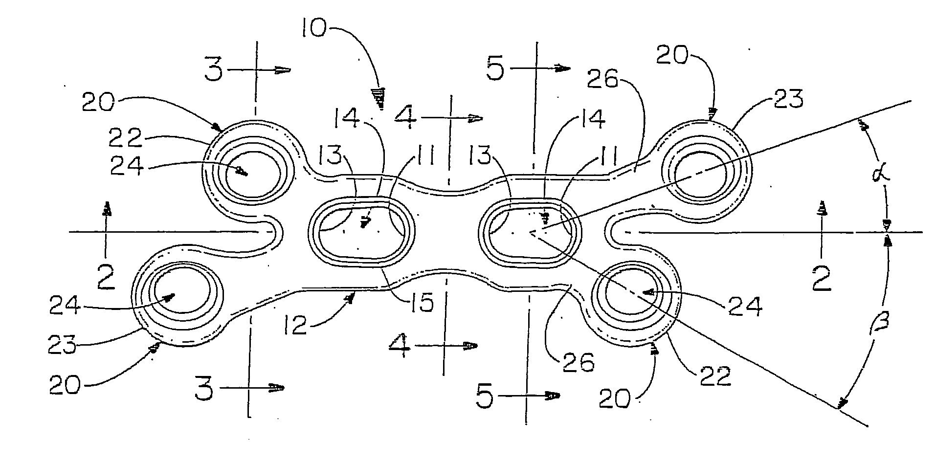
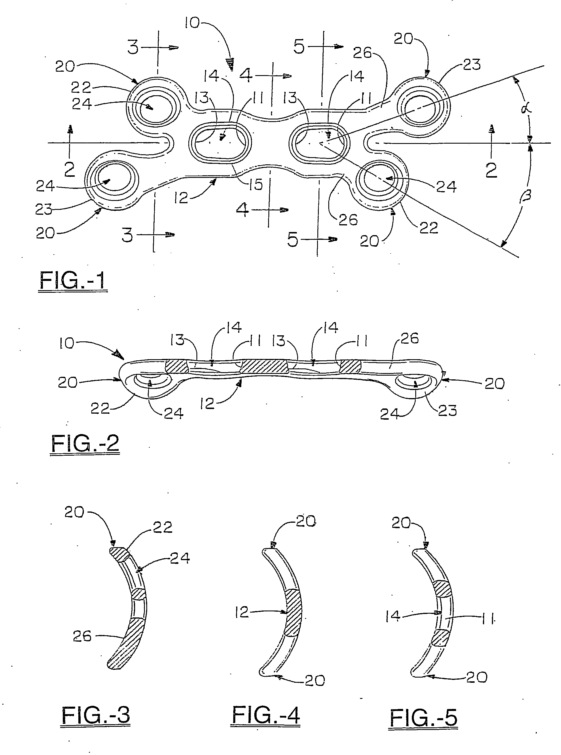
[0045] The plate 10 of the present invention is shown having a asymmetric shape which can be thought of as being similar to the Greek letter X with foreshortened opposing diagonal legs extending from a central trunk portion 12 defining the longitudinal axis of the plate. The trunk portion 12 includes one or preferably more screw holes 14 along the longitudinal axis. The number of screw holes in the trunk portion 12 will depend on the length of the plate, and may range from 0 to 6, and more preferably from 2 to 4. In one embodiment the holes are compression holes. The screw holes 14 are preferably slotted or elongated with a larger radius area 11 on each of the screw holes facing in the same direction, and a smaller radius area 13 which has a shallower lip to allow the plate to be set initially and subsequently to be slide into a different position as the screws are tightened down. This allows compression to be applied across the middle of the trunk section. Further, the screw holes ...


PUM


Abstract

The present invention relates to an orthopedic plate and screw system and instruments for surgical fixation of a small bone or bones including specifically the small bones of the spine. The plate facilitates three dimensional contouring to provide for a variety of applications and to accommodate individual variation in bone shape. The plate has a modified x shape including a central trunk portion including one or more screw holes along a longitudinal axis and a set of divergent upper and an oppositely extending set of divergent lower arms, each arm including screw holes which are placed at a radially equal distance but which diverging asymmetrically from the longitudinal axis relative to its paired upper or lower mate. The screws of the system are self-starting, self-tapping screws including the option of partial or full cannulation. In a further embodiment, the plate is intended for use through the length of the spine.

Description

[0001] THIS APPLICATION IS BASED ON U.S. PROVISIONAL APPLICATION SER. NO. 60 / 648,364, FILED ON JAN. 28, 2005FIELD OF THE INVENTION [0002] The present invention relates to an orthopedic plate for surgical repair or reconstruction of a bone in instances where it is desirable to have convergent screw fixation with screws that placed by the plate so as to be unlikely to impinge on each other. BACKGROUND OF THE INVENTION [0003] The field of orthopedic medicine has grown tremendously in the past fifty years as surgical techniques, implants and instrumentation have developed and been improved. The medical companies have tended to focus their attention on the largest market areas so that some areas of the body, such as the spine, knees and hips, have received intense focus from the large medical companies. While the small bones are frequently subject to the need for re-constructive surgery for example, as a result of trauma, to counteract the effects of aging or to repair congenital deformi...

Claims


Application Information

Patent Timeline
Patent Type & Authority Applications(United States)
IPC IPC(8): A61F2/30
CPCA61B17/8061A61B17/8066A61B17/8085
Inventor KAY, DAVID B.STRNAD, LEE A.DUCHARME, DUSTINWYNKOOP, G. MARTIN
Owner ORTHOHELIX SURGICAL DESIGNS
Why Eureka
Try Eureka