
Audio spectral noise reduction method and apparatus

Inactive Publication Date: 2006-09-07
KOSEK DANIEL A
View PDF59 Cites 63 Cited by
  • Summary
  • Abstract
  • Description
  • Claims
  • Application Information

AI Technical Summary

Benefits of technology

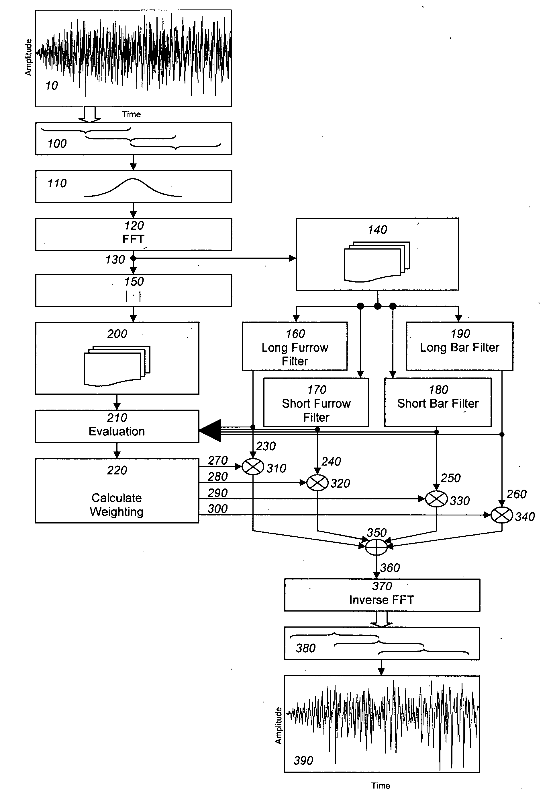
[0031] An optional enhancement to the method of the present invention includes the use of a second pair of time-frequency filters to improve intelligibility of the output signal. More specifically, this second pair of time-frequency filters is used to obtain a rapid transition from a steady-state voiced speech segment to adjacent fricatives or gaps in speech without temporal smearing of the audio signal. The first pair of time-frequency filters described in connection with the main embodiment of the present invention is referred to as the “long-time” filters, and the second pair of time-frequency filters that is included in the enhancement is referred to as the “short-time” filters. The long-time filters tend not to respond as rapidly as the short-time filters to input signal changes, and they are used to enhance the voiced features of a speech segment. The short-time filters do respond rapidly to input signal changes, and they are used to locate where new words start. Transient monitoring is used to detect sudden changes in the input signal, and resolution switching is used to change from the short-time filters to the long-time filters and vice versa.
[0035] An optional enhancement to the system of the present invention further comprises a second pair of time-frequency filters, which are used to improve intelligibility of the output signal. As stated above, this second pair of time-frequency filters is used to obtain a rapid transition from a steady-state voiced speech segment to adjacent fricatives or gaps in speech without temporal smearing of the audio signal. As with the method claims, the second pair of “short-time” filters responds rapidly to input signal changes and is used to locate where new words start. The first pair of “long-time” filters tends not to respond as rapidly as the short-time filters to input signal changes, and they are used to enhance the voiced features of a speech segment. Transient monitoring is used to detect sudden changes in the input signal, and resolution switching is used to change from the short-time filters to the long-time filters and vice versa.

Problems solved by technology

These gaps can occur when the received signal is lost due to channel interference (for example, lightning, cross-talk, or weak signal) in a radio or transmission or decoding errors in the playback system.
Although muting the playback does not solve the problem, it is often used because it is inexpensive to implement, and if the gap is very short, it may be relatively inaudible.
This process can make the received signal sound somewhat less noisy because the hiss goes away during the pause between words or sentences, but it is not particularly effective.
Furthermore, the “pass” mode simply allows the signal to pass but does not actually improve the signal-to-noise ratio when the desired signal is present.
Making the attack and release times somewhat gradual will lessen the audibility of the gain pumping, but it does not completely solve the problem.
The spectral subtraction process can cause various audible problems, especially when the actual noise level differs from the estimated noise spectrum.
In this situation, the noise is not perfectly canceled, and the residual noise can take on a whistling, tinkling quality sometimes referred to as “musical noise” or “birdie noise.” Furthermore, spectral subtraction does not adequately deal with changes in the desired signal over time, or the fact that the noise itself will generally fluctuate rapidly from time to time.
If some signal components are below the noise threshold at one instant in time but then peak above the noise threshold at a later instant in time, the abrupt change in those components can result in an annoying audible burble or gargle sound.
None of these techniques, however, has been wholly successful at eliminating the audible problems.

Method used


Image

  • Audio spectral noise reduction method and apparatus
  • Audio spectral noise reduction method and apparatus
  • Audio spectral noise reduction method and apparatus

Examples


Embodiment Construction

[0092] The current state of the art with respect to noise reduction in analog signals involves the combination of the basic features of the noise gate concept with the frequency-dependent filtering of the spectral subtraction concept. Even this method, however, does not provide a reliable means to retain the desired signal components while suppressing the undesired noise. The key factor that has been missing from prior techniques is a means to distinguish between the coherent behavior of the desired signal components and the incoherent behavior of the additive noise. The present invention involves performing a time-variant spectral analysis of the incoming noisy signal, identifying features that behave consistently over a short-time window, and attenuating or removing features that exhibit random or inconsistent fluctuations.

[0093] The method employed in the present invention includes a data-adaptive, multi-dimensional (frequency, amplitude and time) filter structure that works to ...


PUM


Abstract

A method of reducing noise in an audio signal, comprising the steps of: using a furrow filter to select spectral components that are narrow in frequency but relatively broad in time; using a bar filter to select spectral components that are broad in frequency but relatively narrow in time; analyzing the relative energy distribution between the output of the furrow and bar filters to determine the optimal proportion of spectral components for the output signal; and reconstructing the audio signal to generate the output signal. A second pair of time-frequency filters may be used to further improve intelligibility of the output signal. The temporal relationship between the furrow filter output and the bar filter output may be monitored so that the fricative components are allowed primarily at boundaries between intervals with no voiced signal present and intervals with voice components. A noise reduction system for an audio signal.

Description

BACKGROUND OF THE INVENTION [0001] 1. Field of the Invention [0002] The present invention relates to the field of digital signal processing, and more specifically, to a spectral noise reduction method and apparatus that can be used to remove the noise typically associated with analog signal environments. [0003] 2. Description of the Related Art [0004] When an analog signal contains unwanted additive noise, enhancement of the perceived signal-to-noise ratio before playback will produce a more coherent, and therefore more desirable, signal. An enhancement process that is single-ended, that is, one that operates with no information available at the receiver other than the noise-degraded signal itself, is preferable to other methods. The reason it is preferable is because complementary noise reduction schemes, which require cooperation on the part of the broadcaster and the receiver, require both the broadcaster and the receiver to be equipped with encoding and decoding gear, and the en...

Claims


Application Information

Patent Timeline
IPC IPC(8): G10L21/02
CPCG10L21/0208G10L21/0232
Inventor KOSEK, DANIEL A.MAHER, ROBERT CRAWFORD
Owner KOSEK DANIEL A
Learn More