System and method for separation of a user's voice from ambient sound

a technology for separating user voices and ambient sounds, applied in the direction of earpiece/earphone noise reduction, transmission, intra-aural earpieces, etc., can solve the problems of affecting the stability and hence the attenuation of the hearing protection device, limiting the freedom of movement of users, and limited audio bandwidth, so as to reduce the cost, increase the power, and the effect of more spa

Inactive Publication Date: 2007-07-12
PHONAK
View PDF14 Cites 44 Cited by
  • Summary
  • Abstract
  • Description
  • Claims
  • Application Information

AI Technical Summary

Benefits of technology

[0022] Preferably the audio signal processing unit is integrated within the device. In an alternative embodiment, the audio signal processing unit may be adapted to be worn behind the user's ear or somewhere at the user's body. In this case, although the device becomes more handy, more space, and hence also more power, is available for the audio signal processing unit, which may reduce the costs an / or may improve the performance of the blind source separation. In such case, the audio signal processing unit may be connected to the microphone either by wires, which is the most simple solution, or via a wireless link, for example, a radio frequency link such as Bluetooth link, an inductive link or an infrared link, which solution would result in enhanced wearing comfort for the user.
[0023] As a further alternative, the audio signal processing unit could be designed to be located remote from the user and is connected to the microphones via a radio frequency link such as Bluetooth link. In this case, there would be even less restrictions regarding the size and power consumption of the audio signal processing unit, which might result in reduced costs and / or increased performance of the blind source separation.

Problems solved by technology

Furthermore, for industrial applications boom microphones have the drawbacks that they limit the freedom of movement of the user and that, when combined with a hearing protection device, they will affect the stability and hence the attenuation of the hearing protection device.
Bone-conduction microphones have the drawbacks that they have a very limited audio bandwidth which limits the intelligibility of the speech and that they often have to be pressed fairly hard which causes discomfort to the user.

Method used


Image

  • System and method for separation of a user's voice from ambient sound
  • System and method for separation of a user's voice from ambient sound
  • System and method for separation of a user's voice from ambient sound

Examples


Embodiment Construction

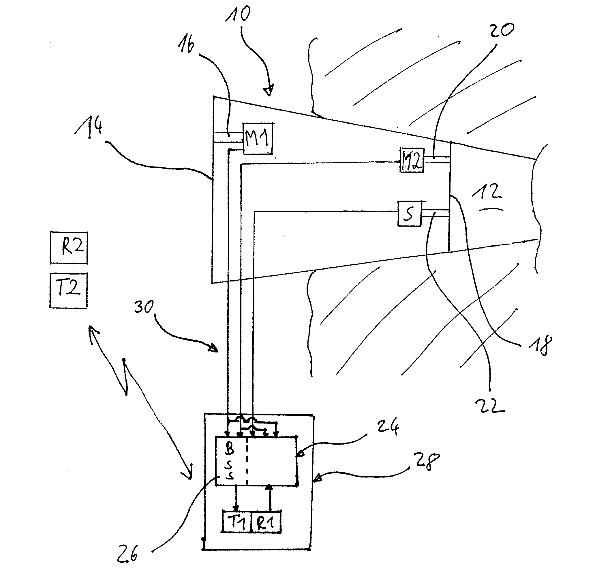
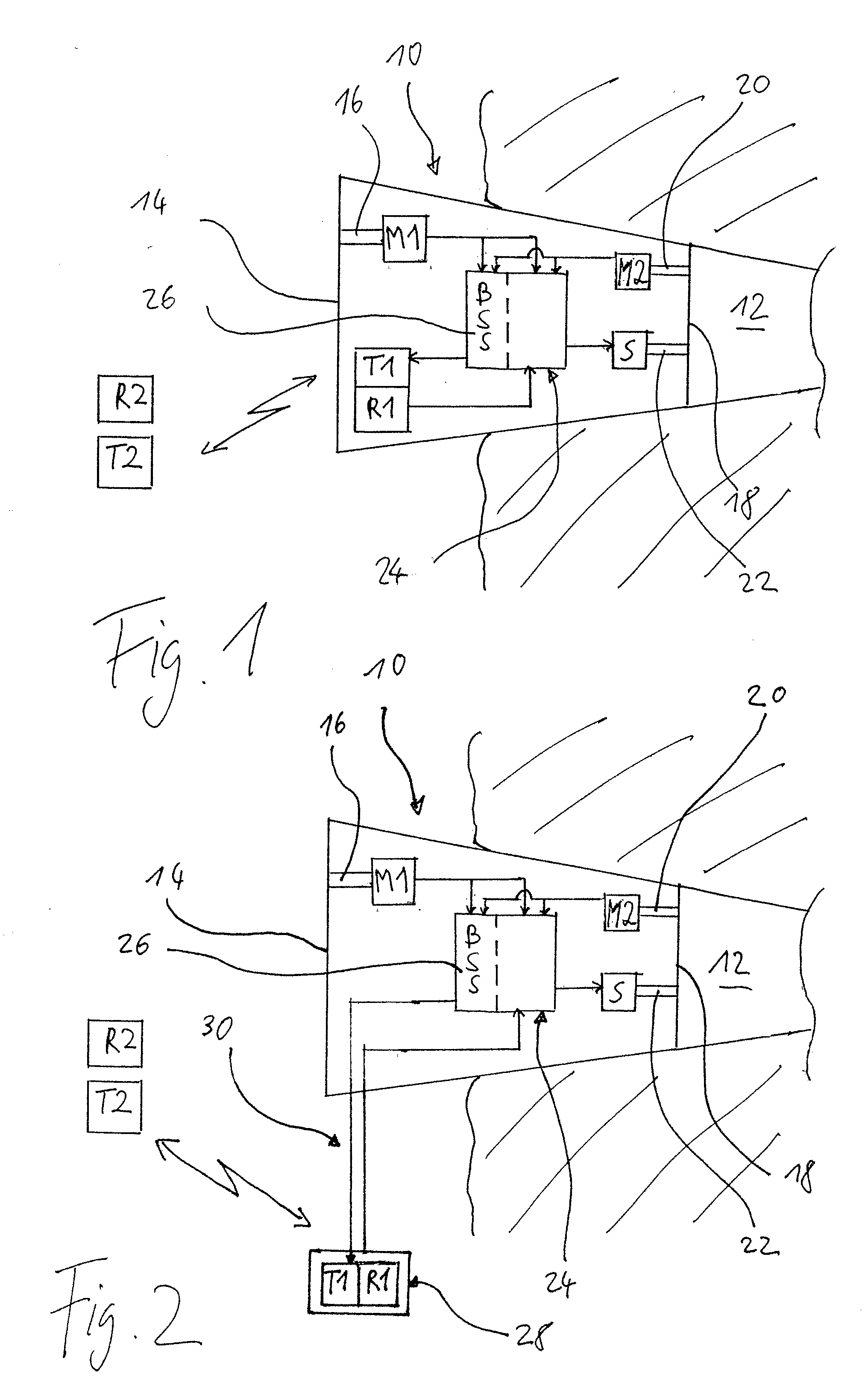
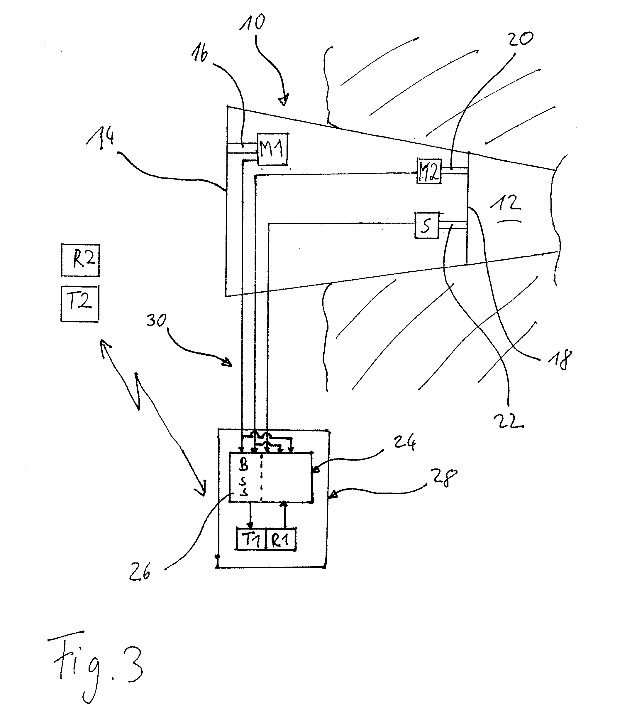
[0037] The system of FIG. 1 comprises a device 10 designed as a hearing protection earplug which may have a hard shell with an elasticity from shore D85 to shore D65, which is customized, i.e. it has an outer shape according to the individual measured inner shape of the user's outer ear and ear canal. The hard shell may be manufactured by layer-by-layer laser sintering of a powder material, for example, polyamide powder, or by laser stereo-lithography or photo-polymerization. An overview regarding such additive layer-by-layer build-up processes for manufacturing customized shells of hearing devices can be found, for example, in US 2003 / 0133583 A1 or U.S. Pat. No. 6,533,062 B1. The inner shape of the person's ear canal and outer ear can be measured, for example, by taking an impression which then undergoes laser scanning or by direct laser scanning of the ear.

[0038] Preferably the hard shell is designed such that it provides for an acoustic attenuation, averaged over the audible fre...


PUM


Abstract

A system for separation of a user's voice from ambient sound, comprising a device to be worn at the user's ear or at least partly in the user's ear canal comprising a first microphone oriented acoustically outwardly towards the environment and a second microphone oriented acoustically inwardly towards the user's ear canal, and an audio signal processing unit for processing audio signals from the first and second microphone by a blind source separation algorithm adapted to separate the user's voice from ambient sound.

Description

BACKGROUND OF THE INVENTION [0001] 1. Field of the Invention [0002] The present invention relates to a system and a method for separation of a user's voice from ambient sound by using at least one device to be worn at the user's ear or at least partly in the user's ear canal. [0003] 2. Description of Related Art [0004] For communication purposes, in particular for wireless electronic communication between or from persons exposed to a noisy environment, such as workers in industrial plants, policemen, soldiers, firemen, etc., it is desirable to have a sound pick-up system which is capable at least to some extent to separate the user's voice from ambient noise, or generally ambient sound, in order to improve the intelligibility of the person's speech to the listener, who may be one of the other persons exposed to the noisy environment or who may be a remote person. [0005] A common approach to achieve such separation of a person's voice is the use of a boom microphone, i.e. a microphon...

Claims


Application Information

Patent Timeline
Patent Type & Authority Applications(United States)
IPC IPC(8): H04R25/00
CPCH04B1/123H04R25/558H04R25/40H04M1/6066H04R1/1016H04R1/1083H04R25/554H04R2201/107H04R25/00
Inventor DIJKSTRA, EVERTHAUTIER, OLIVERDESTREZ, NICOLASPLATZ, RAINER
Owner PHONAK
Why Eureka
Try Eureka