Agricultural sprayer boom and method of manufacture

a sprayer and boom technology, applied in the field of agricultural machinery, can solve the problems of cumbersome and expensive repair, large manpower and time required for its construction, and the residual strain of welding tubular walls, and achieve the effect of facilitating the construction of beams

Inactive Publication Date: 2006-09-14
CAIMAN SOC DE RESPONSABILIDAD
View PDF2 Cites 36 Cited by
  • Summary
  • Abstract
  • Description
  • Claims
  • Application Information

AI Technical Summary

Benefits of technology

[0009] An object of the present invention is to facilitate construction of beams for agricultural sprayer booms strong enough to resist strains and stresses to which the structures are subjected during normal operation.
[0010] Another object of the present invention is to provide a boom beam structure that is not weakened by welding points. And a related object is to enable a beam to be built using other, unweldable materials.
[0014] Complementary beam members include a base plate joining the longitudinal edges of the sidewalls of the profiled member so as to close the open face of the profiled member and form a sturdy box-like structure, and internal cross-platelets joined to the inclined strips of the profiled-member sidewalls to further stabilize (rigidize) the beam structure. The platelets, being inclined to the longitudinal direction of the boom, become thus a functional part of these strips in transmitting strains and stresses throughout the beam structure resulting from intrinsic (weight and bending moment) and extrinsic (e.g. wind, jerks, collisions, etc.) factors. Removable fastener elements such as bolts and nuts, rivets or screws may be used to join the baseplate and the cross-platelets to the profiled member. This eliminates the need of welding and consequential local weak points in addition to simplifying construction and reducing manpower in relation to the forementioned welded tubular structure.
[0015] The height of the side walls advantageously decreases outwardly (i.e. away from the machine) and, likewise, the triangular orifices get gradually smaller. A particular feature of the invention is that the fold lines in the sheet structure are not parallel but slightly offset such that they virtually converge at a point off the beam. This feature facilitates use of a suitable standard folding machine for bending a metal sheet along the fold lines to form the girder of the beam structure. As a result, the shape of the bridge wall is not strictly rectangular but trapeze in fact, gradually broadening in the longitudinal direction away from the machine, i.e. towards the distant end of the beam.

Problems solved by technology

However, its construction requires substantial manpower and time.
Welding generates residual strains in the tubular walls which may break during service.
Repair is likewise cumbersome and expensive.
The boom weighs about 150 kg resulting in a substantial bending moment at the near end, this being a critical zone where the weld may eventually crystallize, leading to breakage.

Method used


Image

  • Agricultural sprayer boom and method of manufacture
  • Agricultural sprayer boom and method of manufacture
  • Agricultural sprayer boom and method of manufacture

Examples


Embodiment Construction

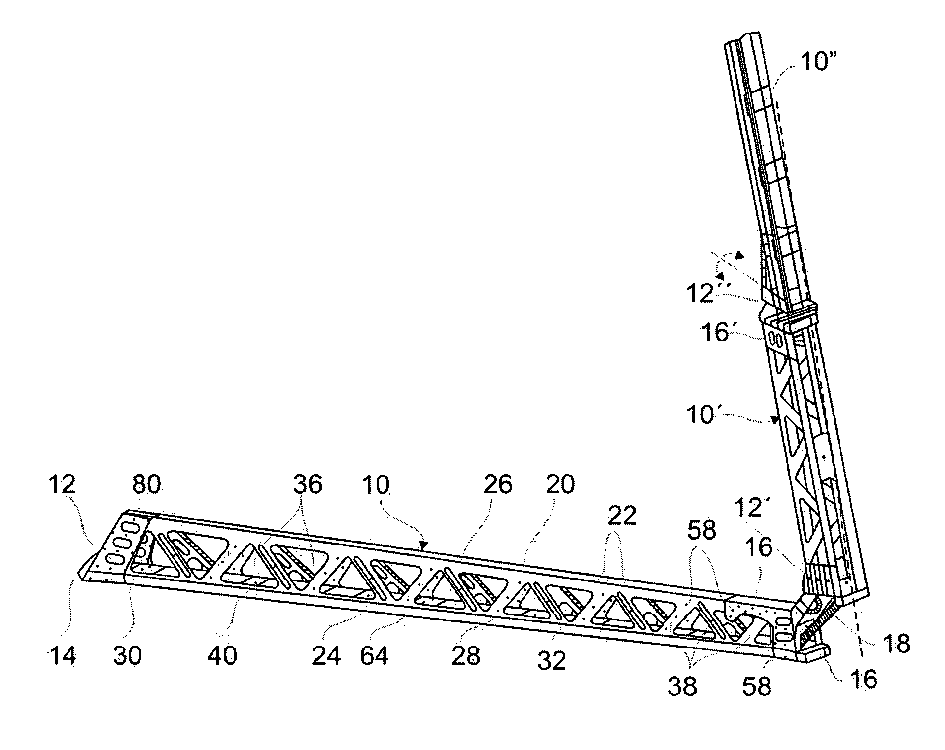
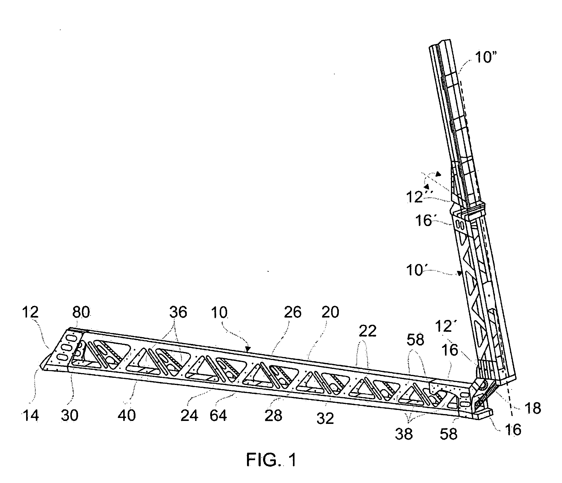
[0031] A boom according to a preferred embodiment of the invention is illustrated in FIG. 1. Two such booms are mounted, one to each side, of a sprayer machine (not illustrated) having an overall operational spray width of 25 meters and carrying a tank for 3,200 liters of spray solution. The boom comprises three beams 10-10′-10″ extending end to end in a longitudinal direction X (the longitudinal direction X of the boom corresponds to the cross-machine direction of the sprayer machine) when the boom is in its unfolded position (which is not the case in FIG. 1). The two innermost beams 10-10′ comprise elongated structures according to the present invention, although the dimensions of the middle beam 10′ are on a reduced scale in relation to the innermost beam 10 of the two. An inner cap 12 is mounted to the near end of the innermost beam 10 and is provided with hinge element 14 for mounting the boom to the sprayer machine. An outer cap 16 is mounted to the distant end of the innermos...


PUM


Abstract

Sprayer boom beam structure includes a girder member having an elongated profiled sheet structure including at least two folds or bends defining three portions in an inverted V- or U- or C-shaped cross-section, i.e. a pair of side or wing walls integrally joined by a top or bridge wall. Triangular orifices are punched out of the side walls, alongside one another in a longitudinal direction, alternating between inverted and upright triangles, leaving inclined strips of sheet material in between, and which absorb and transmit strains and stresses similar to a tubular lattice structure, and having benefits of a spatial lattice-like structure. Complementary beam members include a base plate joining longitudinal edges of sidewalls of the profiled member and close the open face of the profiled member, forming a sturdy box-like structure, and internal cross-platelets joined to inclined strips of the profiled-member sidewalls to further rigidify the beam structure.

Description

CROSS-REFERENCE OF RELATED APPLICATIONS [0001] This application claims priority of Argentine patent application no. P 05 01 00962, filed Jun. 9, 2005, and this application claims priority of Argentine patent application no. P 05 01 00962, filed on Mar. 11, 2005, and each of which is incorporated herein by reference. FIELD OF THE INVENTION [0002] The present invention is related in general to farming machinery, more particularly to boom structures on sprayer machines. BACKGROUND OF THE INVENTION [0003] Sprayer machines carry booms mounting a number of spray nozzles at regular intervals thereon for applying fertilizers, herbicides and the like on crops. The purpose of these beams is proper positioning of the spraying nozzles. Productivity is enhanced using booms on the order of about 25 to 30 meters across, sometimes more for large tracts of farmland. For constructive, operational and practical reasons, the booms are built in sections or modules in the form of beams joined together by...

Claims


Application Information

Patent Timeline
Patent Type & Authority Applications(United States)
IPC IPC(8): E04H12/34
CPCA01M7/0071
Inventor RIVAS, ALBERTOBADALASSI, GABRIEL
Owner CAIMAN SOC DE RESPONSABILIDAD
Why Eureka
Try Eureka