Aircraft ground support cart with component life optimization control

a technology of component life optimization and ground support, which is applied in the direction of cooling fluid circulation, domestic cooling apparatus, lighting and heating apparatus, etc., can solve the problems of increasing the fuel consumption of the apu, adversely affecting the lifetime of the apu or air conditioner module components, and not being desirable, so as to achieve the effect of not adversely affecting the system cost, lifetime, and/or fuel consumption

Inactive Publication Date: 2006-09-14
HONEYWELL INT INC
View PDF41 Cites 32 Cited by
  • Summary
  • Abstract
  • Description
  • Claims
  • Application Information

AI Technical Summary

Benefits of technology

[0007] The present invention provides an aircraft ground support system for supplying electrical power and temperature-controlled air to an aircraft during ground support operations that is simple, efficient, and does not adversely affect system costs, and / or lifetime, and / or fuel consumption.

Problems solved by technology

When actual ambient temperature is below the design ambient temperature, the air conditioner module may supply cooling air at the 100 lb / min flow rate and at a temperature that is less than 55° F. In some instances, supplying air to an aircraft at a flow rate of 100 lb / min and at a temperature less than 55° F. may not be desirable.
In addition, when the actual electrical load being supplied by the APU is below the design electrical load, it may not be needed or desirable, to supply a flow rate of 100 lb / min of cooling air, either above or below 55° F. Nonetheless, current ground power carts are typically configured to supply the full rate of cooling air flow without regard to the ambient temperature or supplied electrical load.
Consistently supplying cooling air at such a relatively high flow rate can adversely impact the lifetime of the APU or air conditioner module components.
This can also result in increased fuel consumption by the APU.

Method used


Image

  • Aircraft ground support cart with component life optimization control
  • Aircraft ground support cart with component life optimization control
  • Aircraft ground support cart with component life optimization control

Examples


Embodiment Construction

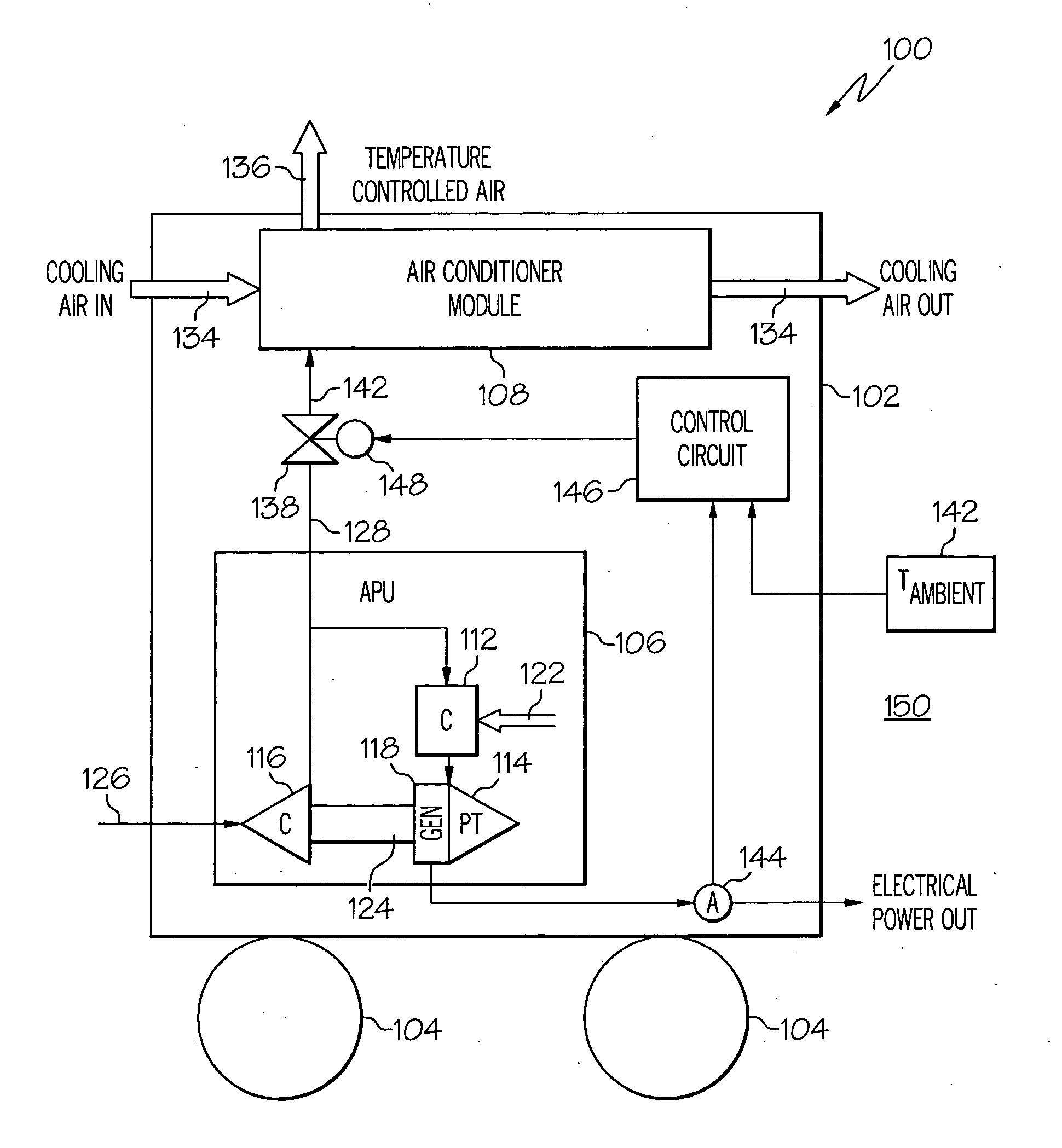
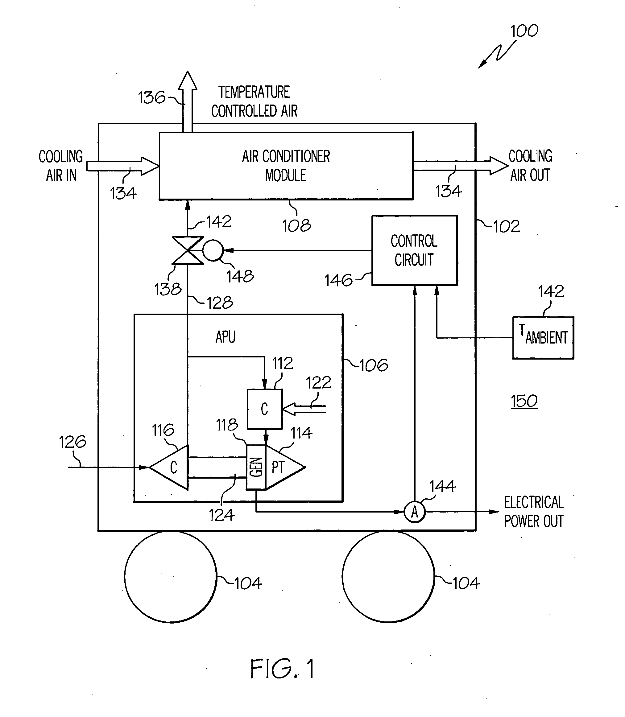
[0015] A simplified schematic representation of an exemplary ground cart 100 is depicted in FIG. 1. The ground cart 100 includes a housing 102 and varying numbers of rotationally mounted wheels 104, which allow the cart 100 to be readily transported to one or more aircraft. Various systems and components may be mounted on or within the housing 102 to generate electrical power and supply conditioned air for aircraft ground support operations. In the depicted embodiment, the ground cart 102 includes an auxiliary power unit (APU) 106 and an air conditioner module 108. It should be appreciated that other systems and components may also be mounted on or within in the ground cart 100, but for the sake of clarity and ease of description, only a single APU 106 and air conditioner module 108 are depicted.

[0016] The general operation and configuration of turbine APUs is well-known in the industry. In the depicted embodiment, the APU 106 includes a combustor 112, a power turbine 114, a compre...


PUM


Abstract

A ground-based system and method of supplying electrical power and temperature-controlled air to an aircraft environmental control system during ground support operations uses a throttle valve to control the flow of compressed air flowing through a heat exchanger. An air conditioner module mounted on a wheeled cart removes heat from the compressed air that is supplied to it from an auxiliary power unit (APU), and supplies cooled compressed air at a desired temperature. The temperature of the cooled compressed air is controlled by selectively positioning a throttle valve, which regulates compressed air flow from the compressed air source. The throttle valve position is controlled in response to one or more ambient meteorological conditions and / or the amount of electrical power being supplied from the system.

Description

TECHNICAL FIELD [0001] The present invention relates to environmental control systems for aircraft and, more particularly, to a ground power cart for efficiently supplying electrical power and temperature-controlled air to an aircraft while it is on the ground. BACKGROUND [0002] Aircraft main engines not only provide propulsion for the aircraft, but in many instances may also be used to drive various other rotating components such as, for example, generators and pumps. The main engines may also be used to supply compressed air to the aircraft's environmental control system, which may be used to supply temperature-controlled air to both the aircraft cabin and to electronic equipment within the aircraft. [0003] When an aircraft is on the ground and its main engines are not being used, an alternative power source may be used to supply electrical power to onboard electrical equipment, such as the aircraft avionics suite. In addition, during some ground support operations, an external su...

Claims


Application Information

Patent Timeline
Patent Type & Authority Applications(United States)
IPC IPC(8): F25D17/04F25D23/12
CPCB64F1/364Y02T50/82Y02T50/80
Inventor LEATHERS, THOMAS M.
Owner HONEYWELL INT INC
Why Eureka
Try Eureka