
Elevator shaft safety net system

a safety net and elevator shaft technology, applied in elevators, building materials handling, construction, etc., can solve the problems of not being able to catch someone or something, unprotected shafts can pose a potential fall hazard, and nothing protects the safety of a person from a fall into the open sha

Inactive Publication Date: 2006-09-14
CURTIS SUSAN +1
View PDF6 Cites 37 Cited by
  • Summary
  • Abstract
  • Description
  • Claims
  • Application Information

AI Technical Summary

Benefits of technology

[0010] It is, therefore, the primary object of the present invention to provide an improved elevator shaft safety net system which uses snap-in closed steel hooks that connect to eye bolts that remain in the elevator shaft so the safety net can be used to catch individuals or equipment falling down the shaft, at all phases of the construction process.
[0011] It is another object of this invention to provide an easy-to-use snap hook system to ensure use by construction workers.
[0013] Yet another object of the present invention is to provide an economical elevator shaft safety net system that is easy to manufacture to provide for widespread, cost-effective use.

Problems solved by technology

Falls from elevation hazards are present at most every jobsite, and many workers are exposed to these hazards daily.
Any unprotected shaft can pose a potential fall hazard.
The aforementioned devices suffer from a number of drawbacks, most notably, they cannot be used to catch someone or something when falling during all phases of construction, especially during finishing and post-construction maintenance.
The aforementioned devices use vertically hung nets which may stop falls by creating a temporary barrier, but when that barrier is removed, nothing protects the safety of a person from a fall into the open shaft.
Furthermore, the aforementioned devices do not use fixed hooks through steel grommets in the entire net which prevent tearing and weakening of the net.

Method used


Image

  • Elevator shaft safety net system
  • Elevator shaft safety net system
  • Elevator shaft safety net system

Examples


Embodiment Construction

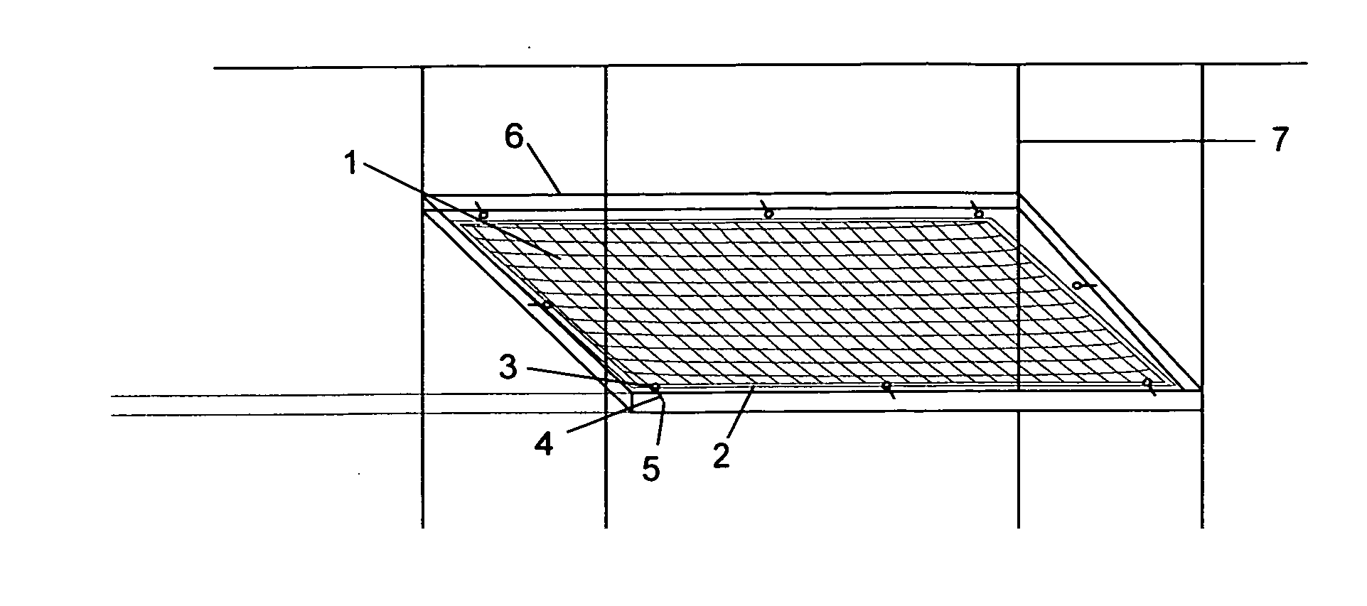
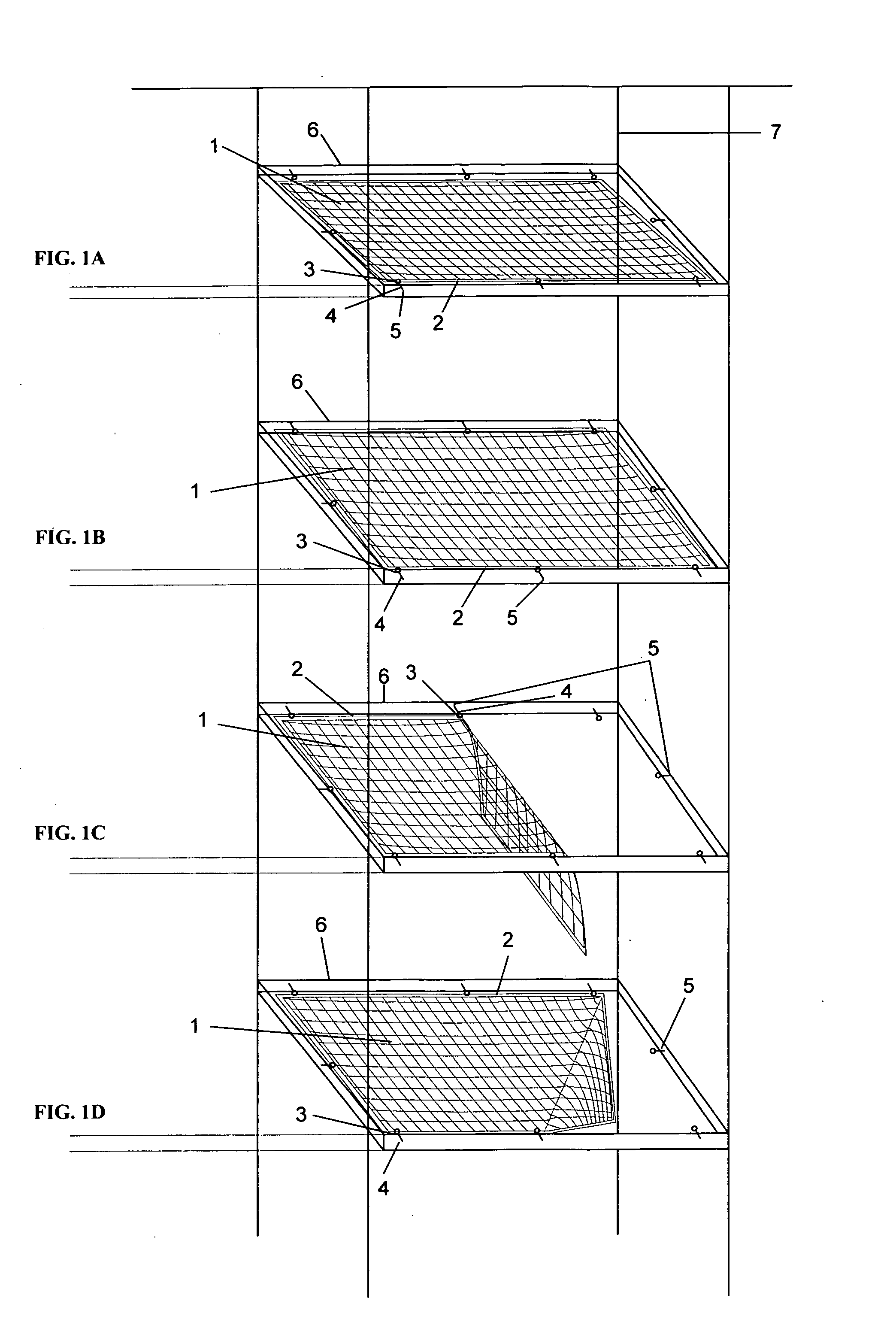
[0027] The present invention is an elevator shaft safety net system. In accordance with a preferred embodiment of the present invention as shown in FIG. 1 (A-D), the elevator shaft safety net system generally comprises a dual-layer net 1 with rope-encased fabric-sealed edges 2 and a plurality of steel grommets 3 attached through the fabric edges 2 around the periphery of the net 1. One or more such nets 1 are attached horizontally within the elevator shaft via a plurality of snap-in locking steel hooks 4 each connected to a corresponding steel grommet 3, the hooks 4 in turn being connected to eye bolts 5 that are screwed into the board / block 6 of the elevator shaft frame below floor level. For each net 1, a total of eight eye bolts 5 are screwed into the four sides of the elevator shaft 7.

[0028] As can be seen in FIGS. 1A, 1B, 1C and 1D, the net 1 is attached by eight spring-lock steel hooks 4 hooked around eight corresponding steel grommet 3, the other end of hooks 4 being attache...


PUM


Abstract

An elevator safety net system for preventing people, equipment, or debris from falling down commercial or residential elevator shafts during building construction, in each case avoiding injury. The net is a high-quality synthetic double-layer net with reinforced borders encased in fabric-sealed edges, and a plurality of steel grommets around the edges of the safety net. A plurality of safety nets may be suspended laterally up and down an elevator shaft before the elevator is installed, and this is done by screwing in eight eye bolts around the elevator shaft so that the safety net can be attached / suspended by snapping in closed steel hooks that connect the eye bolts to corresponding steel grommets of the net, thereby suspending the nets up and down the elevator shaft. The nets can be removed and reinstalled for future maintenance of the elevator shaft by snapping the hooks on and off the eye bolts screwed into the elevator shaft. Thus, if someone or something falls into the elevator shaft during post-construction maintenance, the net will be available to catch the person or thing without harm to themselves or others.

Description

CROSS-REFERENCE TO RELATED APPLICATION(S) [0001] The present application derives priority from U.S. provisional application No. 60 / 661,589 filed Mar. 14, 2005.BACKGROUND OF THE INVENTION [0002] 1. Field of the Invention [0003] The present invention relates to a safety net system for catching objects falling down open elevator shafts, and more particularly to catching an individual and / or equipment falling in a residential or commercial elevator shaft during all stages of construction, including post-construction maintenance. [0004] 2. Description of the Background [0005] Falls from elevation hazards are present at most every jobsite, and many workers are exposed to these hazards daily. Any unprotected shaft can pose a potential fall hazard. In the construction industry, falls lead all other causes of occupational death. For this reason, the Occupational Safety and Health Administration (OSHA) publishes regulations (set forth in 29 CFR), which include Standard Number: 1926.501, the “...

Claims


Application Information

Patent Timeline
IPC IPC(8): A62B1/22
CPCA62B1/22B66B5/005E04G21/3261E04G21/3266
Inventor CURTIS, SUSANDYPSKY, DAVID K.
Owner CURTIS SUSAN
Learn More