Electro-optic delay line frequency discriminator

a delay line and frequency discriminator technology, applied in the field of electro-optic delay line frequency discriminators, can solve the problems of laser noise degrading the signal-to-noise ratio at the output of the discriminator, the output of a laser exhibits relative intensity noise (rin), and the noise of lasers, so as to reduce noise

Inactive Publication Date: 2006-09-14
AGILENT TECH INC
View PDF4 Cites 14 Cited by
  • Summary
  • Abstract
  • Description
  • Claims
  • Application Information

AI Technical Summary

Benefits of technology

[0008] The present invention provides an electro-optic delay line discriminator that is substantially immune to laser RIN, and a method for reducing noise in an electro-optic delay line discriminator.
[0010] In the first path, the optical delay line follows the electrical-to-optical converter. Accordingly, the corresponding optical signal in the first path is delayed; and, hence, the converted first corresponding electrical signal is delayed. In the second path, however, the optical delay line precedes the electrical-to-optical converter. Accordingly, the second corresponding optical signal is not delayed; and hence, the second corresponding electrical signal is not delayed, thus providing a proper condition for operation of the detector.

Problems solved by technology

Electrical delay line discriminators implement the delay with an electrical transmission line; however, if good low frequency response is needed, the electrical transmission line is generally quite long and introduces substantial signal loss, resulting in poor signal-to-noise ratio.
An electro-optic delay line discriminator usually employs a laser to provide an optical signal source; however, the output of a laser exhibits relative intensity noise (RIN).
In conventional electro-optic delay line discriminators, this laser noise degrades the signal-to-noise ratio at the output of the discriminator.
There is a trade-off in laser design between low RIN versus size, power complexity and cost.

Method used


Image

  • Electro-optic delay line frequency discriminator
  • Electro-optic delay line frequency discriminator
  • Electro-optic delay line frequency discriminator

Examples


Embodiment Construction

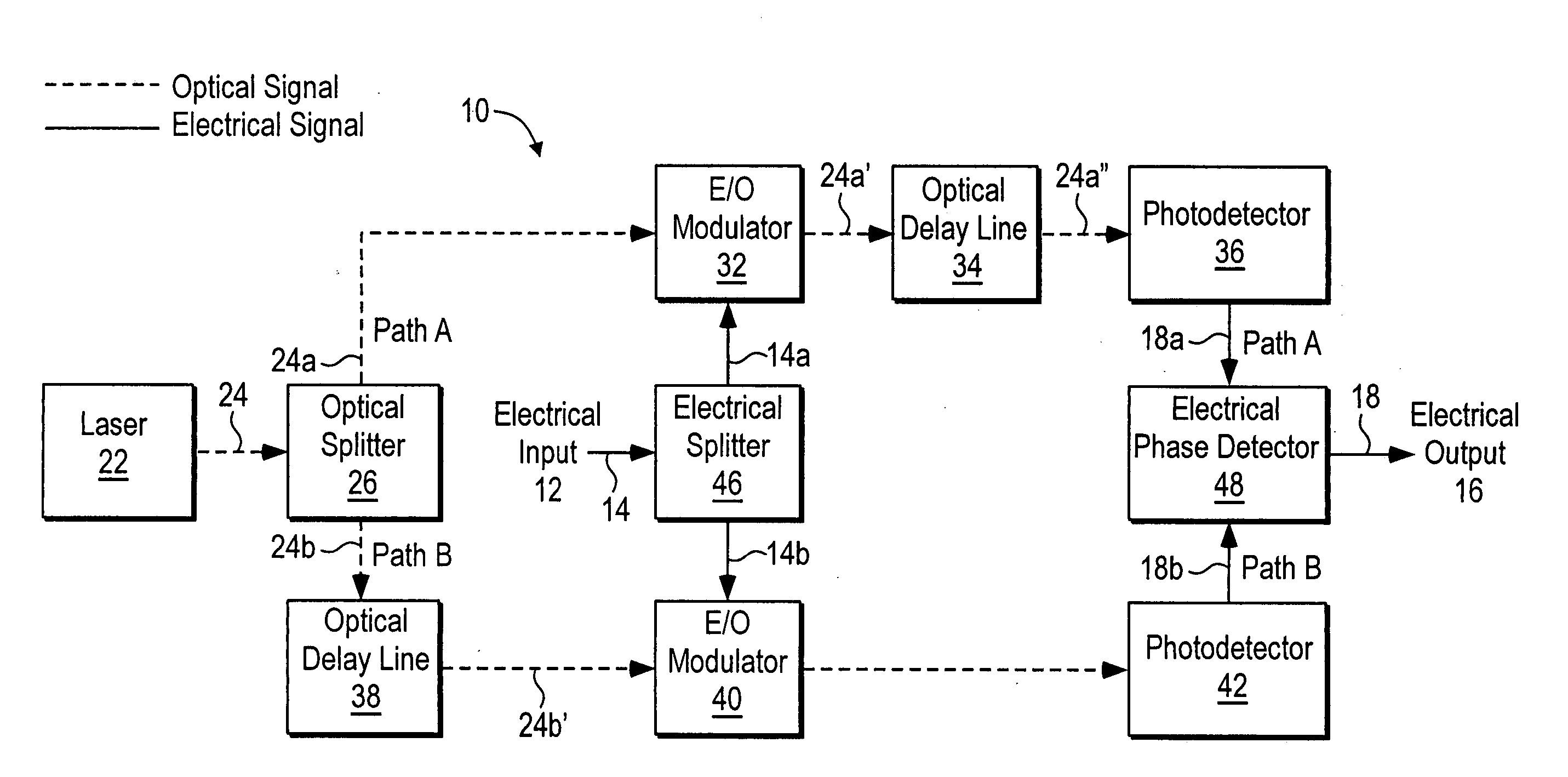
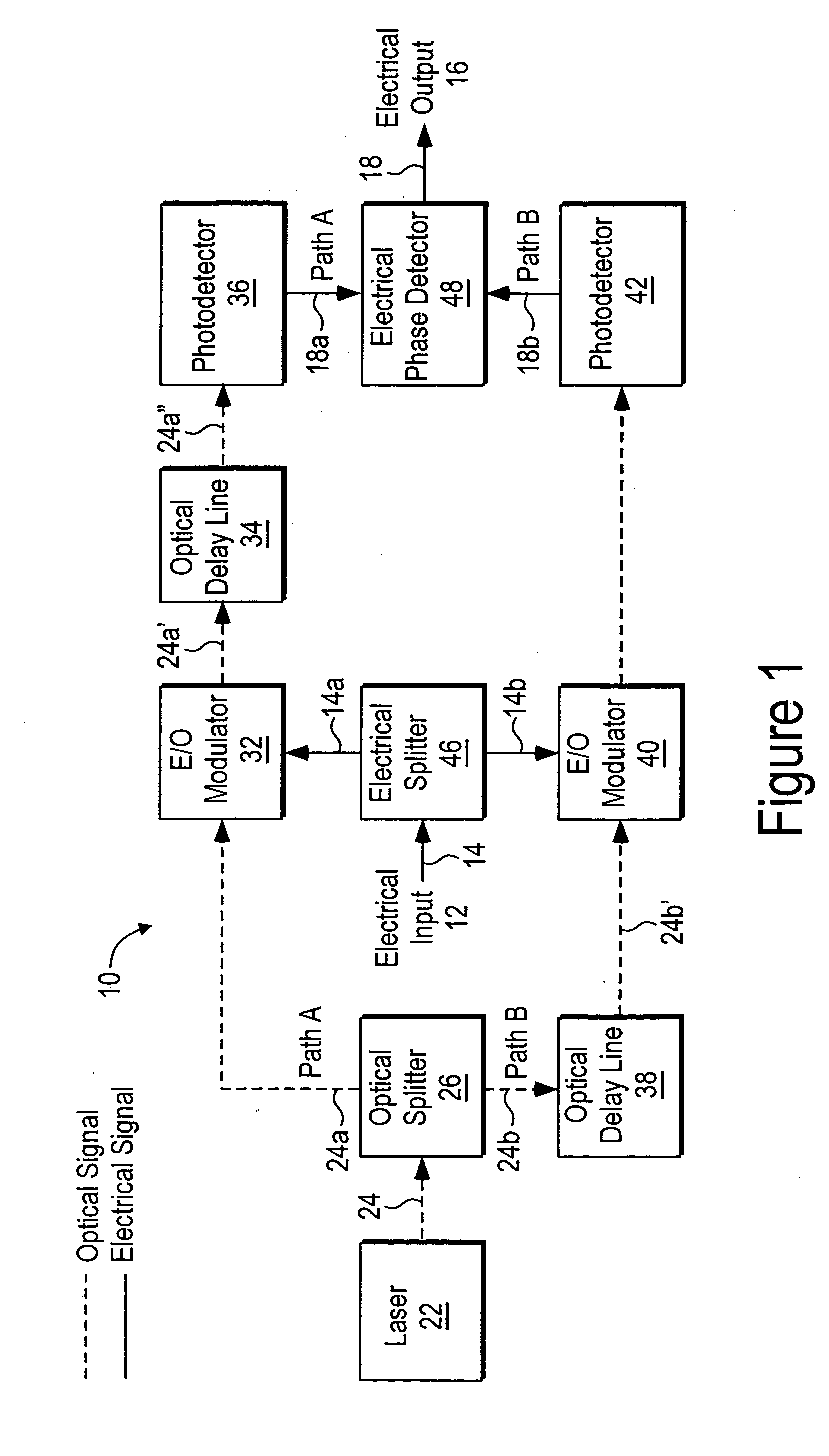
[0017] Embodiments in accordance with the invention provide an electro-optic delay line discriminator, and a method for reducing noise in an electro-optic delay line discriminator.

[0018]FIG. 1 is a block diagram that schematically illustrates an electro-optic delay line discriminator according to an embodiment of the invention. The electro-optic delay line discriminator is generally designated by reference number 10, and has electrical input 12 for inputting electrical signal 14 into the discriminator, and electrical output 16 for outputting electrical signal 18 from the discriminator. Electro-optic delay line discriminator 10 also has laser optical signal source 22 to provide optical signal 24 in the discriminator (in FIG. 1, electrical signals traveling through electro-optic delay line discriminator 10 are represented by solid lines, and optical signals traveling through the discriminator are represented by dashed lines).

[0019] Optical signal 24 is split into two optical signals...


PUM


Abstract

An electro-optic delay line frequency discriminator has an optical signal source providing first and second optical signals that are directed along first and second paths, respectively. In the first path, the first optical signal is converted to a first corresponding optical signal that corresponds to an electrical input signal, and the first corresponding optical signal is then delayed. In the second path, the second optical signal is delayed, and the delayed second optical signal is then converted to a second corresponding optical signal that corresponds to the electrical input signal. The first and second corresponding optical signals are converted to first and second corresponding electrical signals, respectively; and a detector, responsive to the first and second corresponding electrical signals, provides an electrical output signal from the discriminator. Optical source relative intensity noise (RIN) is canceled out and does not degrade the signal-to-noise ratio of the discriminator output.

Description

BACKGROUND OF THE INVENTION [0001] 1. Technical Field of the Invention [0002] The present invention relates generally to the field of delay line frequency discriminators. More particularly, the invention relates to an electro-optic delay line frequency discriminator, and to a method for reducing noise in an electro-optic delay line frequency discriminator. [0003] 2. Background of the Invention [0004] A frequency discriminator (hereinafter referred to as a “discriminator”) performs frequency demodulation, producing an output signal that is proportional to an input frequency. A particular type of discriminator, a delay line discriminator, uses a transmission line to produce a delay. The basic principle of operation of a delay line discriminator is that the phase shift of the output signal of a delay line is proportional to frequency. The phase of the delayed signal is compared to the phase of the undelayed signal at the input to the delay line by a phase detector. The output of the ph...

Claims


Application Information

Patent Timeline
Patent Type & Authority Applications(United States)
IPC IPC(8): H01J40/14
CPCG01R23/17G01R23/175
Inventor KARLQUIST, RICHARD K.
Owner AGILENT TECH INC
Why Eureka
Try Eureka